Pump impeller

A pump impeller and vane pump technology, which is applied in the direction of pumps, pump control, pump components, etc., can solve the problems of vane pump assembly difficulties, pump impeller manufacturing difficulties, etc., reduce the risk of cavitation, simple assembly, and increase the delivery volume Effect

Inactive Publication Date: 2009-08-05
GM GLOBAL TECH OPERATIONS LLC
View PDF4 Cites 2 Cited by
  • Summary
  • Abstract
  • Description
  • Claims
  • Application Information

AI Technical Summary

Problems solved by technology

As the elastic part is an integral component of the impeller, assembly of vane pumps becomes difficult because pump vanes that fit loosely in the vane slots can jump out of the vane slots when the impeller is fitted into the casing ring
In addition, the manufacture of the pump wheel also becomes difficult

Method used


Image

  • Pump impeller
  • Pump impeller
  • Pump impeller

Examples


Embodiment Construction

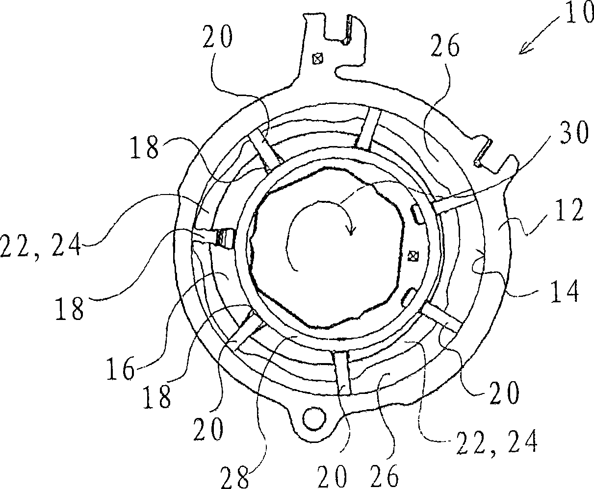
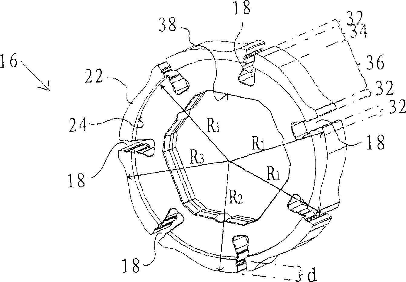
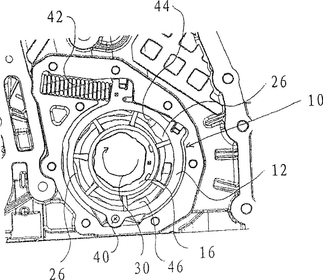
[0021] figure 1 The illustrated vane pump 10 has a housing ring 12 with a circular inner contour 14 . The pump impeller 16 is mounted eccentrically in the housing ring 12 relative to the housing ring. The pump wheel 16 has a plurality of vane slots 18, each of which has a pump vane 20 installed therein. Formed between two adjacent vane grooves 18 is a chamber wall 22 which has an axially protruding land 24 with respect to the other pump wheel 16 . The chamber wall 22 , the respective pump blades 20 belonging to the chamber wall and the inner contour 14 of the housing ring 12 form a delivery chamber 26 .

[0022] An elastic positioning ring 28 is arranged radially inside the pump vane 20, which is closely attached to the radially inward surface of the pump vane 20, so as to squeeze the pump vane 20 radially outward, thereby pumping the pump even at low speeds. The blades 20 also bear against the inner contour 14 of the casing ring 12 . The movement of the positioning ring 2...


PUM


Abstract

The invention relates to a pump impeller (16) of vane pump (10) comprising a plurality of vane troughs (18) for supporting pump vanes (20) at least moving radially and a chamber wall (22) formed between two adjacent vane troughs (18) for forming a convey chamber (26), characterized in that the chamber wall (22) has an axial protruding ring bank (24) that limits movement of a position ring (28) for radial movement of the pump vanes (20) and has a first wall block (32) that supports each pump vane (20) in the vane troughs (18) reliably, a second block (34) for forming thickness (d) of the ring bank (24) to support a sintering tool (16) reliably and a third block (36) for forming an enlarged conveying chamber volume. Therefore, the pump impeller (16) can be simply manufactured and has an enlarged convey amount when the structural space is identical.

Description

technical field [0001] The invention relates to a pump wheel of a vane pump. In order to suck fluid, the pump wheel can be rotatably installed in the casing of the vane pump. Background technique [0002] A vane pump with a pump impeller is known, for example, from DE 10 2005 048 602 A1, which has a plurality of vane grooves for supporting radially movable pump vanes. A cavity wall is formed between two adjacent vane slots. A part of the delivery chamber of the vane pump can be formed by means of the chamber wall. The delivery chamber is formed between the circular peripheral surface of the pump impeller, the pump blades and the circular inner surface of the casing ring which are arranged eccentrically with respect to the pump impeller, wherein the circular peripheral surface of the pump impeller forms the cavity walls between the blade grooves separated by vane slots. [0003] It is known from DE 10142712 A1 that the pump blades are loaded with spring force, so that the ...

Claims


Application Information

Patent Timeline
Patent Type & Authority Applications(China)
IPC IPC(8): F04C2/344
CPCF01C21/0836F01C21/0809F04C14/226F04C2/3442F04C2/086F04C2240/20F04C2230/22
Inventor 乔格·赫德里奇
Owner GM GLOBAL TECH OPERATIONS LLC
Why Eureka
Try Eureka