Square optical glass lens and method of producing the same

A technology of optical glass and manufacturing method, which is applied to glass manufacturing equipment, glass pressing, manufacturing tools, etc., and can solve problems such as lack of exhaust effect, difficulty in lens assembly, poor exhaust effect, etc.

Inactive Publication Date: 2009-07-29
E PIN OPTICAL IND
View PDF22 Cites 2 Cited by
  • Summary
  • Abstract
  • Description
  • Claims
  • Application Information

AI Technical Summary

Problems solved by technology

However, in the prior art in which the exhaust passage is provided in the molding equipment, if the cross-sectional area of ​​the passage is large enough, it can approach the preferred δ value, but at this time, a large amount of molten glass will infiltrate into the passage to form a side skirt, resulting in a Afterwards, secondary processing is required to cut off the side skirt; and in the prior art in which several grooves are preset in the lower mold core to form air passages, although it can prevent the glass material from pressing the air passages and hindering the exhaust, but in the forming Several convex bodies will be formed on the lens, which will cause difficulty in lens assembly, and if the cross-section of the groove of the lower mold core is shallow and small, the δ value is too low and the exhaust effect will be lacking; the method of having grooves on the lower mold core is applied in Multi-cavity molding, because the air channel in the center of the multi-cavity is too long, the exhaust effect is not good

Method used


Image

  • Square optical glass lens and method of producing the same
  • Square optical glass lens and method of producing the same
  • Square optical glass lens and method of producing the same

Examples


no. 1 example

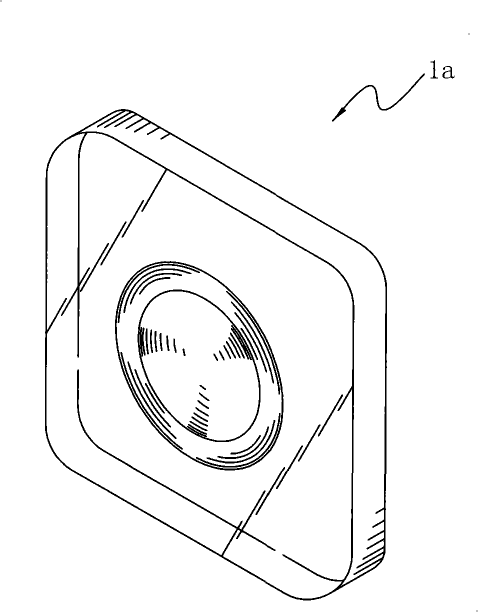
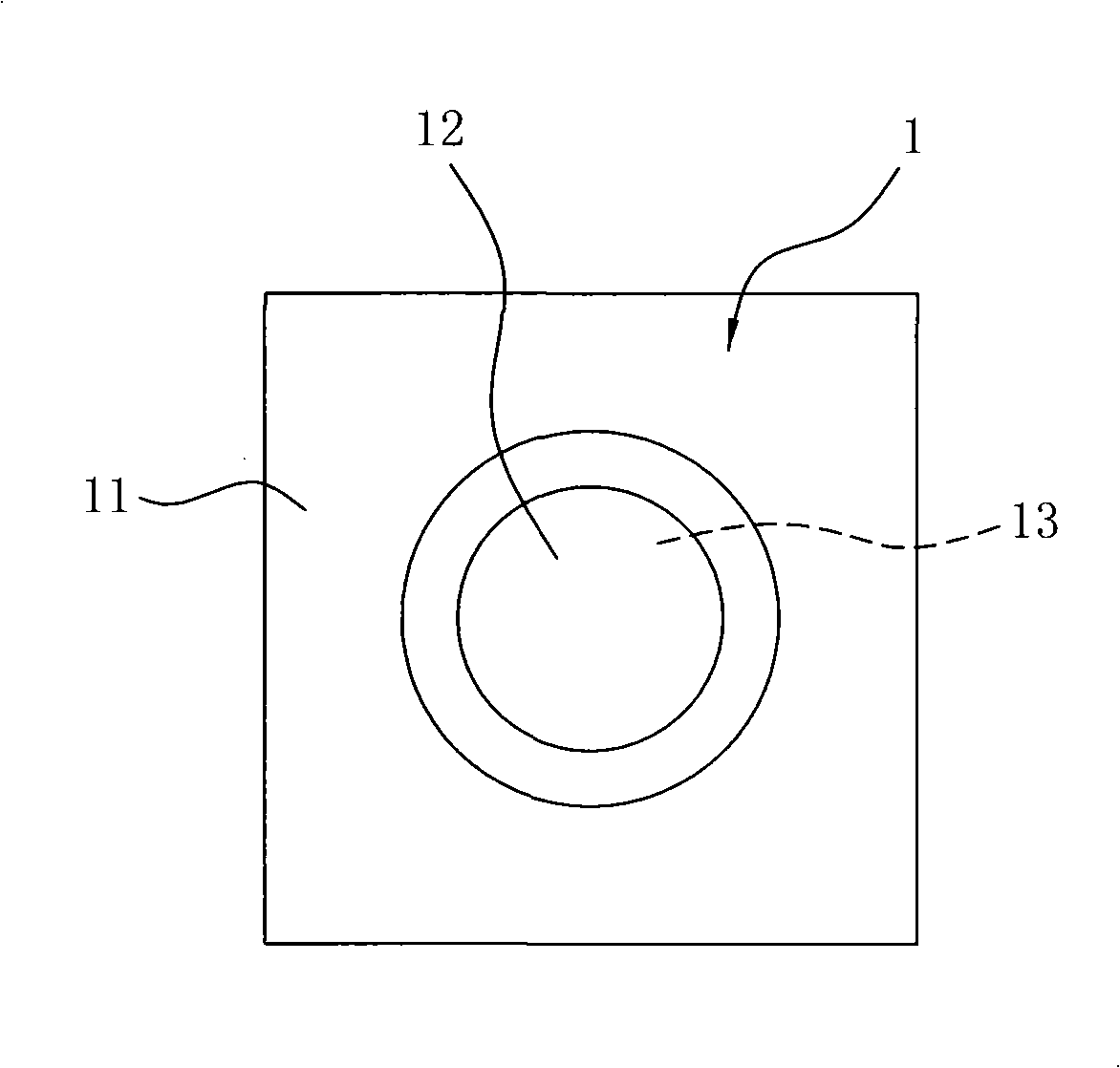
[0040] This embodiment is applied to a concave-convex aspherical square optical glass lens 1 such as image 3 , Figure 4 As shown, it is composed of a first optical surface 12, a second optical surface 13 and a shoulder 11, wherein the first optical surface 12 is a convex and aspheric surface, and the second optical surface 13 is a The surface is concave and aspherical, and the shoulder 11 is square and the four corners are all right angles, that is, the aforementioned right-angled square shoulder 11 .

[0041] In the square optical glass lens 1 of the present embodiment, its focal length is 1.87 mm, when assembled in the lens group 3 as shown in Figure 5, 6, can be applied to the diagonal size is 1 / 7 " (inch) below CMOS sensing assembly. The aspheric surface parameters of the convex aspheric surface of the first optical surface 12 of the present embodiment and the concave aspheric surface of the second optical surface 13 are as Table 1, and the aspheric surface formula used...

no. 2 example

[0060] This embodiment is applied to a biconvex aspheric square optical glass lens 1 as shown in Figure 10 and Figure 11, which is composed of a first optical surface 12, a second optical surface 13 and a rectangular square shoulder 11. Composition, wherein, the first optical surface 12 is a convex aspheric surface, the second optical surface 13 is a convex aspheric surface, the right-angle square shoulder 11 is square and the four corners are all right angles.

[0061] In the square optical glass lens 1 of the present embodiment, its focal length is 1.796mm, when assembled in the lens group 3 such as Figure 12 , Figure 13 , can be applied to CMOS sensing components with a diagonal size of 1 / 10 "(inch). The first optical surface 12 and the second optical surface of this embodiment are both convex aspheric surfaces, and the aspheric surface of the convex aspheric surface The parameters are shown in Table 2, and the aspheric formula used is the aspheric formula (1) described ...

no. 3 example

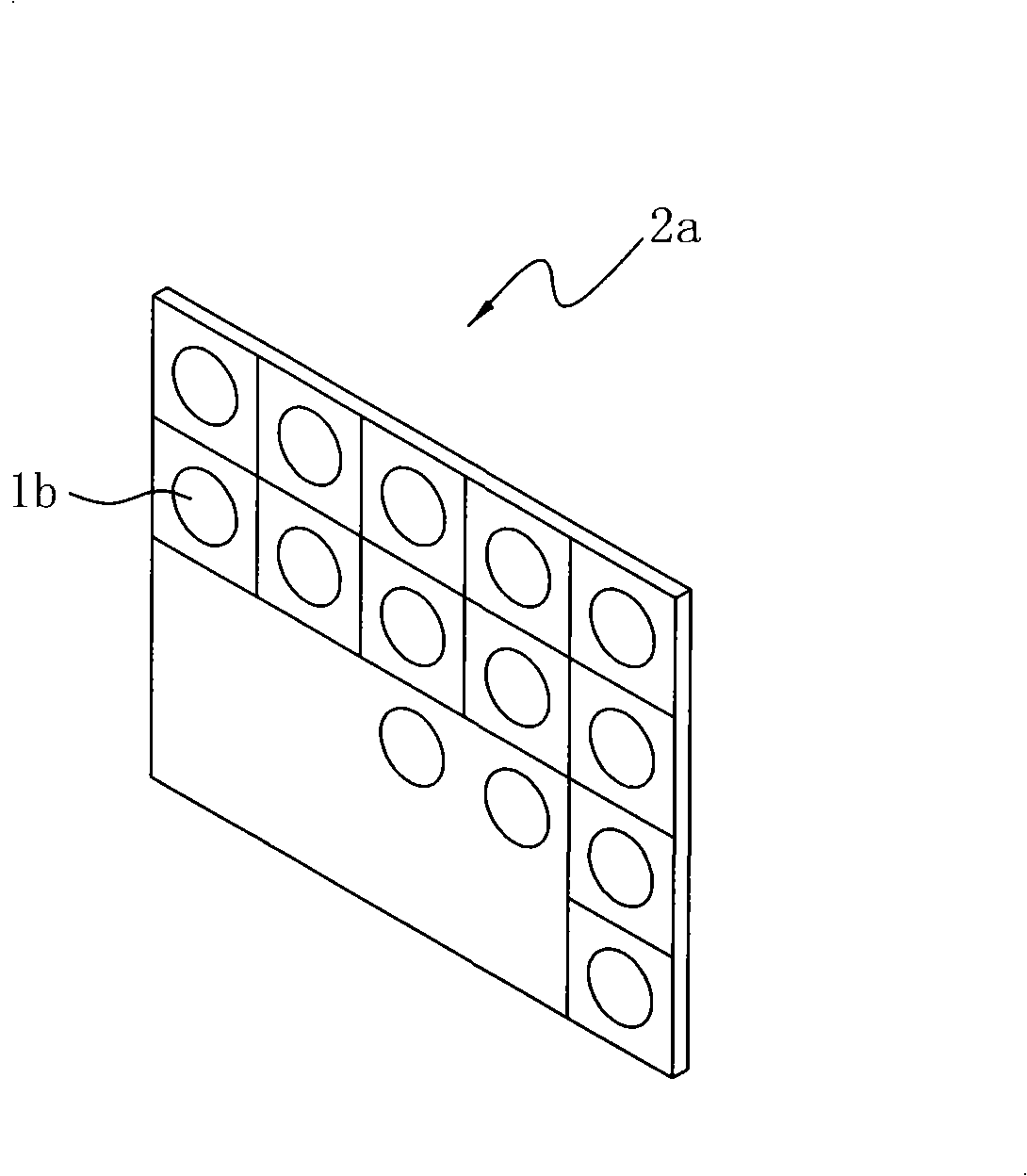
[0068] The present embodiment is to utilize the molding die that is provided with convex body to manufacture a square optical glass lens 1 such as Figure 17 shown. In the existing glass lens molding process, when the glass preform is placed into the mold cavity of the forming mold, there is generally a vacuuming process, the purpose of which is to discharge excess air in the mold cavity and avoid air residue Bubbles are caused in the mold cavity and affect the accuracy. Because the glass material will press the lower mold core to cause the air in the mold cavity of the lower mold core to be difficult to get rid of, there are many techniques to overcome this problem in the molding process of a single mold cavity; however, in the molding process of multiple mold cavities as in the present invention, That is, multi-cavity glass molding (multi-cavityglass molding), the gas removal is not easy. refer to Figure 14 and Figure 9 As shown, the lower mold core 52 of the forming d...


PUM


Abstract

The invention relates to a square optical glass lens and a method for manufacturing the same. The square optical glass lens comprises a first optical surface, a second optical surface and a right angle square shoulder part, wherein the first optical surface and the second optical surface can be formed by a spherical surface or a non-spherical surface; and the right angle square shoulder part can be arranged in a lens base of a lens group. The method for manufacturing the square optical glass lens comprises the following steps: using a square glass as a raw material; making use of a multi-die-cavity forming die to model multi-die-cavity modeling glass into a multi-lens lens blank; separating the lens blank into individual square optical glass lenses; and providing a convex body in the multi-die-cavity forming die in order to avoid air bubbles caused by residual air to influence the precision of the optical surfaces in the glass modeling process so that the air in the molding process can be discharged out through the clearance formed by the height fall around the convex body. The square optical glass lens manufactured by the method not only has precise optical precision, but also greatly simplifies the prior monomer processing of the square optical glass lens so as to reduce the manufacturing cost.

Description

technical field [0001] The invention relates to a square optical glass lens and a manufacturing method thereof, especially a low-cost square optical glass lens with a precise optical surface and a right-angled square shoulder, which is used in mobile phone cameras and CCD (charge Coupled device, charge-coupled device) or CMOS (complementary metal-oxide-semiconductor, complementary metal single metal oxide semiconductor) and other sensing components on the camera. Background technique [0002] With the advancement of technology, electronic products are constantly developing towards thinner, smaller and multi-functional. In electronic products, such as digital still camera, PC camera, network camera, mobile phone Devices such as personal digital assistants (PDA) all have the requirement of adding an imaging device; and in order to be convenient to carry and meet the needs of humanization, the imaging device not only needs to have good imaging quality, but also needs to have a ...

Claims


Application Information

Patent Timeline
IPC IPC(8): C03B11/08
Inventor 徐三伟
Owner E PIN OPTICAL IND
Why Eureka
Try Eureka