
Multi-color biosensor

A detector and radiation beam technology, applied in the field of optical detection, to achieve high sensitivity, reduce the amount of aberration, reduce the effect of spherical aberration and chromatic aberration

Inactive Publication Date: 2009-07-22
KONINKLIJKE PHILIPS NV
View PDF1 Cites 2 Cited by
  • Summary
  • Abstract
  • Description
  • Claims
  • Application Information

AI Technical Summary

Problems solved by technology

The disadvantage of the above-mentioned device is that the chromatic aberration of the confocal lens is ignored, which will limit the simultaneous multi-color detection

Method used


Image

  • Multi-color biosensor
  • Multi-color biosensor
  • Multi-color biosensor

Examples


Embodiment Construction

[0045] The present invention will be explained with reference to specific embodiments and with reference to specific drawings, but the present invention is not limited thereto, which is only defined by the claims. Any reference signs in the claims do not constitute a limitation on the scope of the invention. The drawings described are only schematic and not restrictive. In the drawings, for illustrative purposes, the size of some elements may be enlarged and not drawn to scale. Where the term "comprising" is used in this specification and claims, it does not exclude other elements or steps. When an indefinite article or a definite article is used to indicate a singular noun such as "a" or "the", it includes a plurality of such nouns, unless there are other special instructions.

[0046] In addition, the terms first, second, third, etc. in the specification and claims are used to distinguish between similar elements, and are not necessarily used to describe the order of before and ...


PUM


Abstract

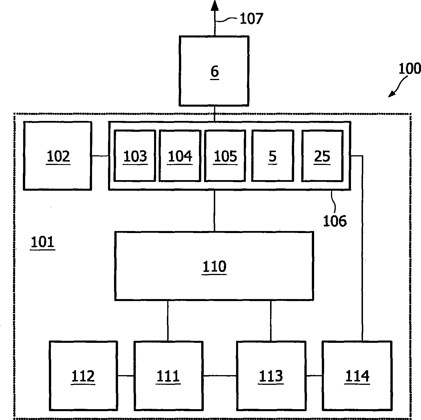
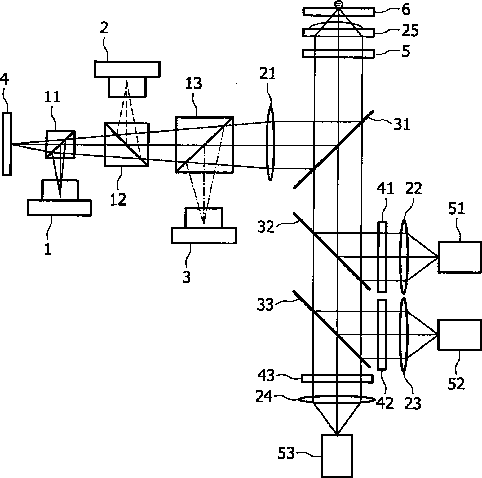
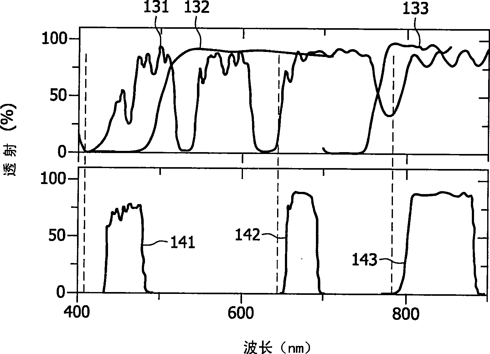
A detection system is described (100) for detecting luminescence sites on a substrate (6). The detection system (100) typically comprises an irradiation unit (102) for generating at least one excitation irradiation beam for exciting luminescence sites on the substrate (6). The at least one excitation irradiation beam may be a plurality of excitation irradiation beams. The detection system (100) also comprises a first optical element, e.g. refractive element (25), adapted for receiving at least two irradiation beams of different wavelengths or wavelength ranges, the at least two irradiation beams being excitation irradiation beam(s) to be focused on a substrate and / or luminescence irradiation beam(s) to be collected from the excited luminescence sites on the substrate (6). The detection system (100) also comprises an optical compensator for adjusting at least one of the at least two irradiation beams of different wavelengths or wavelength ranges so as to reduce or compensate for optical aberrations. The present invention also relates to a corresponding method for detecting, a phase plate and a method for designing such a phase plate.

Description

Technical field [0001] The invention relates to the field of optical detection. More specifically, the present invention relates to a method and system for optical detection. For example, the optical detection can be (for example) qualitative or quantitative detection using a pair of particles or fluorophores (for example) in biological, chemical or biochemical analysis. The luminescence signal used in the detection, and involves the means for improving this detection method and system. Background technique [0002] (US6617590) describes an image reading device, which includes three laser sources, a scanning mechanism that uses laser beams emitted from the laser sources to scan the surface, a photodetector, and a light guide for transferring the image from the image carrier. Lead to the confocal optical system of the photodetector. The device specifies several related detection technologies, such as microarray imaging, autoradiography imaging, chemiluminescence imaging, and the l...

Claims


Application Information

Patent Timeline
Patent Type & Authority Applications(China)
IPC IPC(8): G01N21/64G02B27/00
CPCG01N2021/6419G01N2021/6441G01N21/6428G01N2021/6421G01J3/10G01J3/36G01J3/021G01J3/4406G01N21/645G01N2021/6463G01J3/02
Inventor E·M·H·P·范戴克M·I·博安法R·温贝格尔-弗里德尔
Owner KONINKLIJKE PHILIPS NV
Learn More