
Voice coil type focus motor

A technology of voice coil motor and coil, which is applied in the direction of casing/housing/support, electrical components, electromechanical devices, etc., which can solve the extremely high precision requirements of the yoke ring, the design size of the device is difficult to further reduce, and cannot be completely Shield electromagnetic radiation and other problems, achieve the effect of simple shape, small design size and guaranteed assembly accuracy

Inactive Publication Date: 2009-07-22
李俊
View PDF6 Cites 32 Cited by
  • Summary
  • Abstract
  • Description
  • Claims
  • Application Information

AI Technical Summary

Problems solved by technology

The core of this technical solution is that the coil must move in the concave-shaped gap, and the cylindrical yoke ring is stretched inside the square outer shape. Therefore, there are still four cross-sectional air gaps in the magnetic circuit, and it is still difficult to further reduce the design size of the device. Small, very high requirements on the accuracy of the parts of the device, especially the accuracy of the yoke ring
In addition, there is no yoke plate at the open end of the square outline to form a closed magnetic circuit with it, so it cannot completely shield electromagnetic radiation
Also, this technical solution does not consider that the lens driving device automatically limits the rotation of the lens support when the lens is installed.

Method used


Image

  • Voice coil type focus motor
  • Voice coil type focus motor
  • Voice coil type focus motor

Examples

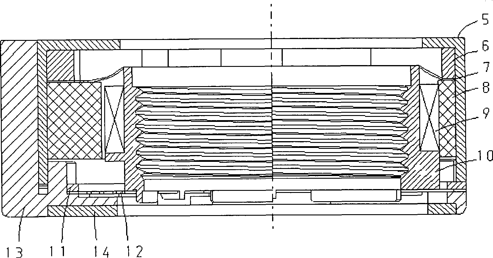

Embodiment Construction

[0026] The present invention is suitable for cameras with automatic focus function, and is specifically applied to mobile phones, cameras, video cameras or detection sensor vision systems, robot vision systems and other equipment with camera functions to drive lens displacement to achieve focus lens driving device.

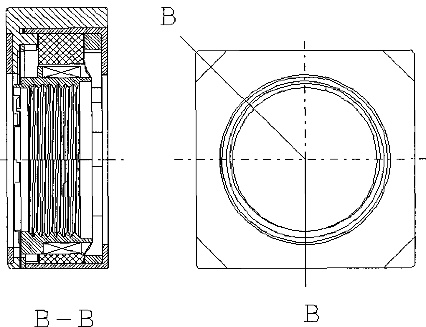
[0027] The present invention will be described in detail below in conjunction with the embodiment of the accompanying drawings, please refer to figure 1 and figure 2 schematic diagram.

[0028] The lens driving device of the present invention comprises: a polyhedron casing 5, a substrate 13 matched with the casing 5, a yoke plate 14 embedded in the substrate 13, a magnet 8 and a coil 9 arranged in the casing 5, and a lens support 10 arranged inside the coil 9 The upper and lower ends of the lens support body 10 are respectively provided with an upper elastic piece 7 and a lower elastic piece 12 to support its movement, an upper supporting piece 6 for positioning...


PUM


Abstract

A voice coil motor comprises a stator which is a reverse L-shaped magnetic yoke and also can be taken as a shell. The voice coil motor is characterized in that one end is provided with an opening, and the other end is not completely closed and provided with a hole; magnetite is placed on the inner wall of the shell; a base plate is matched with the shell, and a lower magnetic yoke plate is arranged on the base plate; a rotor drives a coil to be wound on a lens supporting body of an outer cylindrical surface; the connecting way is that the rotor is hung inside a stator by an upper plate type shrapnel and a lower plate type shrapnel; a frame of the upper shrapnel is fixed by an upper support chip and the magnetite, and the circular arc at the inner side is bonded with the upper end part of the lens supporting body; a frame of the lower shrapnel is fixed by a lower support chip, and the circular arc at the inner side is bonded with the lower end part of the lens supporting body. By utilizing a closed magnetic circuit formed by the reverse L-shaped shell and the magnetic yoke plate, the voice coil motor improves the stability of the magnetic circuit; the closed metal space region can be used for preventing electromagnetic radiation; the shell serves as an assembled framework, and the coil is directly wound on the cylindrical surface of the lens supporting body, so that the number of air gaps among movable bodies in the magnetic circuit is reduced. Therefore, the voice coil motor has the advantages of compact structure, low processing difficulty of the parts, simple assembly technology and strong practicability.

Description

technical field [0001] The present invention relates to a sound map motor, in particular to a camera for auto-focus function, which is specifically applied to mobile phones, cameras, video cameras or detection sensor vision systems, robot vision systems and other equipment with camera functions to drive lens displacement so as to A lens drive device for focusing. Background technique [0002] The similar lens driving device adopted by existing domestic and foreign miniature cameras mostly adopts the public scheme in "Lens Driving Device" published by Chinese Patent Publication No. CN 1683946A, which includes a cylindrical yoke ring installed on the substrate, A magnet and a coil are placed in the yoke ring, and a lens with a lens support is arranged on the inner peripheral side of the coil; the cross section of the cylindrical yoke ring is in a concave shape, and the magnet and coil are placed in the concave cylindrical shape. Inside the yoke ring, the coil is fixed on the ...

Claims


Application Information

Patent Timeline
Patent Type & Authority Applications(China)
IPC IPC(8): H02K33/18H02K3/00H02K5/22
Inventor 李俊
Owner 李俊
Learn More