Bus interface and method for implementing hot-plug

A bus interface, hot-swappable technology, applied in the field of hot-swappable bus interface, to achieve the effect of simple, low-cost, and widening the scope of application

Inactive Publication Date: 2009-07-15
ZHEJIANG UNIV +1
View PDF0 Cites 5 Cited by
  • Summary
  • Abstract
  • Description
  • Claims
  • Application Information

AI Technical Summary

Problems solved by technology

[0004] The embodiment of the present invention provides a bus interface and method for realizing hot swapping, which solves the problem of needing to use a dedicated hot swapping chip to realize hot swapping, and is simple to implement

Method used


Image

  • Bus interface and method for implementing hot-plug
  • Bus interface and method for implementing hot-plug
  • Bus interface and method for implementing hot-plug

Examples


Embodiment Construction

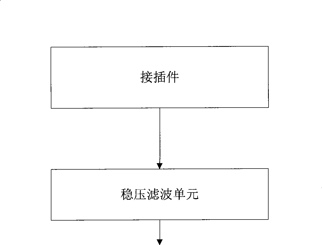
[0028] The embodiment of the present invention provides a bus interface for realizing hot plugging. The structural diagram of the bus interface is as follows: figure 1 As shown, including the connector and the voltage stabilization filter unit, where:

[0029] Connectors are used to realize the hot plugging of ground wires, power wires and signal wires, connect the card and the bus, and control the power-on sequence of the cards according to the length and position of the pins;

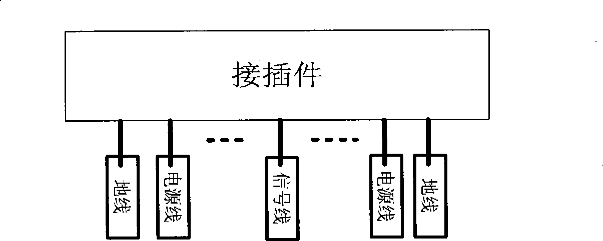
[0030] The pins of the connector include pins connected to ground wires, pins connected to power lines and pins connected to signal lines;

[0031] The voltage stabilizing filter unit is used to connect with the pin wire connecting the power line, and keep the input voltage of the card stable when the card is hot-swapped;

[0032] The card is a master card or a slave card.

[0033] The schematic diagram of the structure of the connector is as figure 2 As shown, the pins connected to the ground wir...


PUM


Abstract

An embodiment of the invention provides a bus interface for realizing hot plug and a method thereof. The hot plug can be realized through the electrifying sequence of restricting cards without a special hot plug chip. The invention settles the problem that the special hot plug chip is required for realizing hot plug in prior art. The hot plug is better realized and the bus stability is greatly increased.

Description

technical field [0001] The invention relates to the communication field, in particular to a bus interface and method for realizing hot plugging. Background technique [0002] High-speed serial bus is used for high-speed data transmission between cards (including master card and slave card). In practical applications, it is often necessary to hot-swap the card, which can quickly change the card on the bus and is easy to use; most of the existing bus interfaces do not support the hot-swappable function, but the bus interface that supports the hot-swappable function Most of them use dedicated hot-swappable chips, which can strictly control the power-on sequence, and the implementation is troublesome. Usually, the price of dedicated hot-swappable chips is relatively high, and the cost of the card increases. [0003] Therefore, the defect of the prior art is that a dedicated hot-swappable chip needs to be used to realize hot-swapping, the power-on sequence is strictly controlled...

Claims


Application Information

Patent Timeline
Patent Type & Authority Applications(China)
IPC IPC(8): G06F13/40
Inventor 施一明王为民张安坤张晓刚黄文君
Owner ZHEJIANG UNIV
Why Eureka
Try Eureka