
Current distribution measuring method and apparatus for fuel cell

A fuel cell and current distribution technology, applied in the direction of measuring device, measuring electricity, measuring electrical variables, etc., can solve the problems of high manufacturing cost, complicated use, and difficult processing, and achieve high practical value, easy to manufacture, and simple structure. Effect

Inactive Publication Date: 2009-07-15
TSINGHUA UNIV
View PDF0 Cites 14 Cited by
  • Summary
  • Abstract
  • Description
  • Claims
  • Application Information

AI Technical Summary

Problems solved by technology

Disadvantages of adopting split flow channel technology are: difficult processing, complex use, cross-gas flow between flow channels, and cannot be independent of the proton exchange membrane fuel cell body
This method has several disadvantages: first, the glass has low strength and high brittleness, so attention should be paid to its safety; second, due to the thermal inertia of the material, the response speed from current to temperature is very slow, and the delay is generally on the order of seconds, which is difficult to reflect Transient Variations in Current Distribution
[0013] (1) The production cost is high and the processing is difficult;
[0014] (2) Inconvenient to use;
[0016] (4) The measurement component is not a device independent of the proton exchange membrane fuel cell

Method used


Image

  • Current distribution measuring method and apparatus for fuel cell
  • Current distribution measuring method and apparatus for fuel cell
  • Current distribution measuring method and apparatus for fuel cell

Examples


Embodiment

[0070] The test procedure for measuring the current distribution inside the fuel cell is:

[0071] Confirm that the packaging of the fuel cell 7 does not use soft magnetic materials or easily magnetizable materials as cover plates;

[0072] When measuring the current distribution of the fuel cell, the measurement control board 4 is fixed on the surface of the fuel cell 7;

[0073] During the measurement, the excitation source 2 outputs the excitation sinusoidal excitation current and adds it to the excitation coil of the magnetic ring, generating an alternating magnetic field to saturate it in the magnetic ring, and the magnetic field generated by the distributed current inside the fuel cell is superimposed on the magnetic ring, affecting the magnetic ring The degree of saturation affects the waveform and harmonics of the induced electromotive force in the measurement coil.

[0074] The induced electromotive force in the measuring coil is sent to the data acquisition processi...


PUM


Abstract

The invention discloses a method and apparatus for measuring the fuel cell internal current distribution, belonging to the technical field of the clean energy proton exchanging film fuel battery test. When measuring the current distribution of the fuel cell, fixing the measuring control plate on the surface of the fuel cell; exerting the energized sine exciting current outputted by the exciting source on a energizing coil of a magnetic ring to generate a saturated alternating magnetic field in the magnetic ring; overlapping the magnetic field generated by the fuel cell interior distribution current on the magnetic ring to enable the excited waveform and harmonic of the magnetic field alternating-current component in the saturation state to be changed; obtaining the overlapped exterior magnetic field through measuring the change by the coil; then demodulating the current size of the area corresponding to the magnetic ring by the formula in the measuring principle. The method of the invention can be used for monitoring whether the local bad change exists or not, can prevent the fault and the danger of total current caused by overlarge local current density under normal range. The measuring apparatus has characteristics of simple structure, low cost and being easy to make.

Description

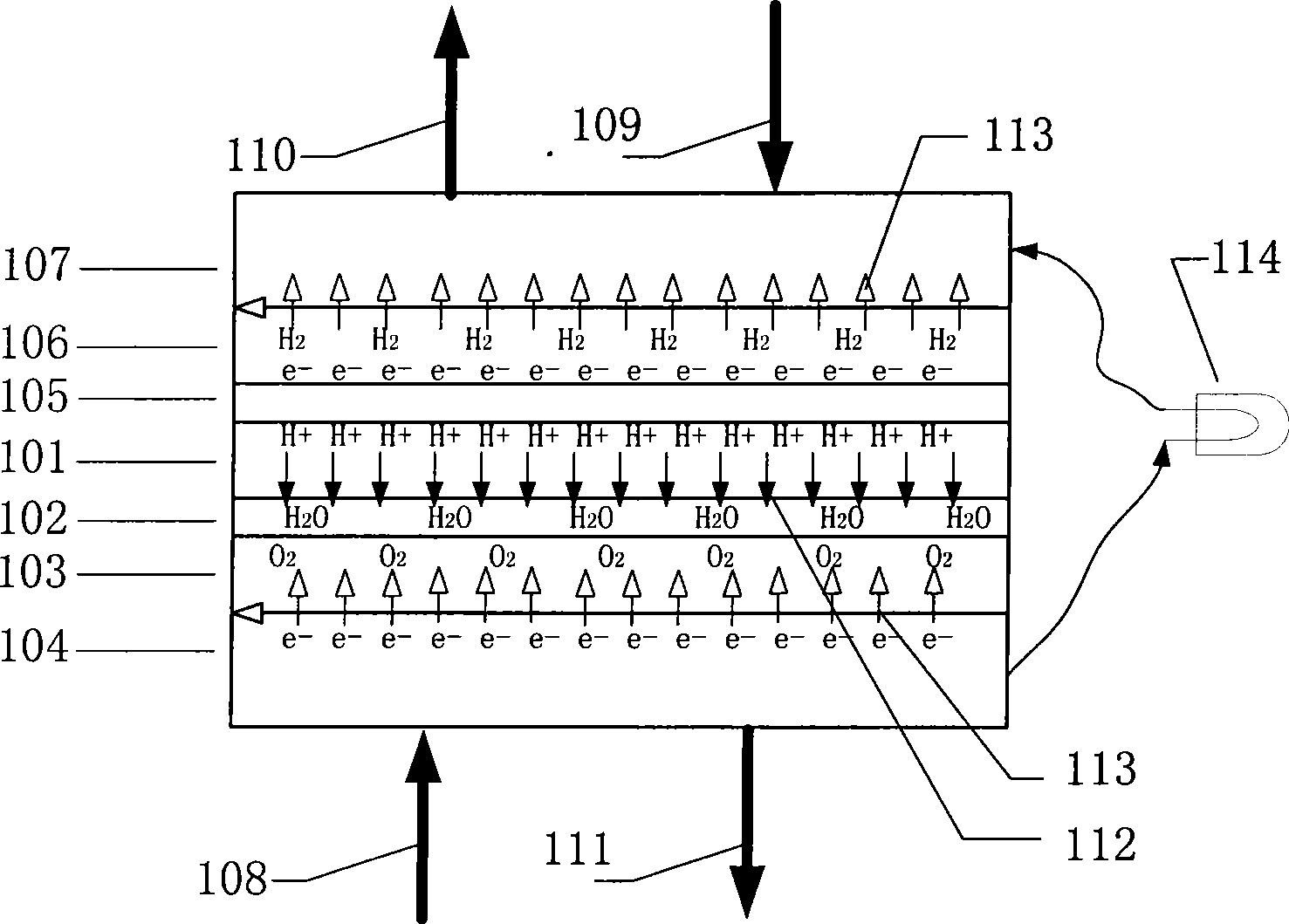
technical field [0001] The invention belongs to the technical field of clean energy proton exchange membrane fuel cell testing, in particular to a method and device for measuring the internal current distribution of a fuel cell, in particular to measuring the internal current distribution of a proton exchange membrane fuel cell by using a magnetic field method. Background technique [0002] A proton exchange membrane fuel cell (PEMFC) is a device that converts chemical energy directly into electrical energy. Here is a brief description of its structure and working principle in conjunction with the accompanying drawings: [0003] Such as figure 1 As shown, the proton exchange membrane fuel cell is composed of membrane electrodes and bipolar collector plates and other components. Wherein the membrane electrode includes proton exchange membrane 101, cathode catalyst layer 102, cathode diffusion layer 103, anode catalyst layer 105, anode diffusion layer 106; The current plate...

Claims


Application Information

Patent Timeline
IPC IPC(8): G01R31/36G01R19/00G01R33/02
Inventor 仝猛裴普成殷丹韩毅赵伟郭军杰吴永平黄海燕包磊杨福源卢兰光李建秋欧阳明高
Owner TSINGHUA UNIV
Learn More