
Texturing machine

A deformation machine and machine technology, which is applied in the field of deformation machines, can solve the problems that cannot be adjusted independently, and achieve the effect of improving the effect of thermal barrier, reducing insulation cost and high insulation effect

Inactive Publication Date: 2009-07-08
OERLIKON TEXTILE GMBH & CO KG
View PDF2 Cites 4 Cited by
  • Summary
  • Abstract
  • Description
  • Claims
  • Application Information

AI Technical Summary

Problems solved by technology

Individual adjustment of the work groups within the machine halves is therefore not possible

Method used


Image

  • Texturing machine
  • Texturing machine
  • Texturing machine

Examples


Embodiment Construction

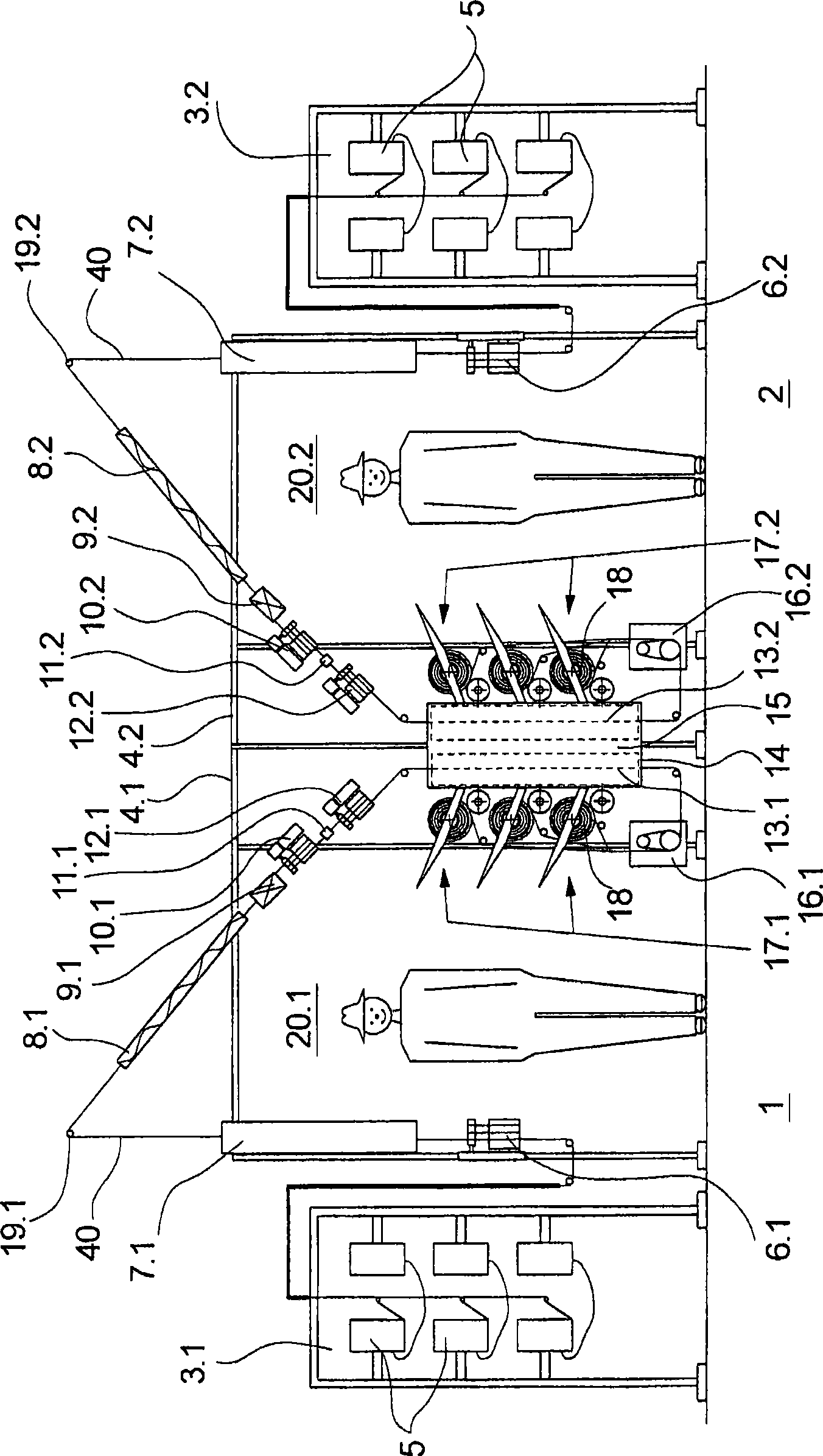
[0024] exist figure 1 The middle diagram shows a cross-sectional view of a first exemplary embodiment of the texturing machine according to the invention. The texturing machine has two mirror-symmetrical machine halves arranged side by side. The left-hand machine half is designated with reference numeral 1 and the right-hand machine half is designated with reference numeral 2 . In the further course of the description, the working units and plant parts assigned to the respective machine half are additionally provided with the reference numeral 1 or 2 to identify the associated machine half.

[0025] Each machine half 1 and 2 comprises a plurality of processing stations in order to deform and wind up one filament in each processing station. exist figure 1 In the view shown in , the filament flow of a processing station is shown in each machine half 1 and 2 . Machine halves 1 and 2 in longitudinal direction—on figure 1 The middle drawing plane is the same as the transverse ...


PUM


Abstract

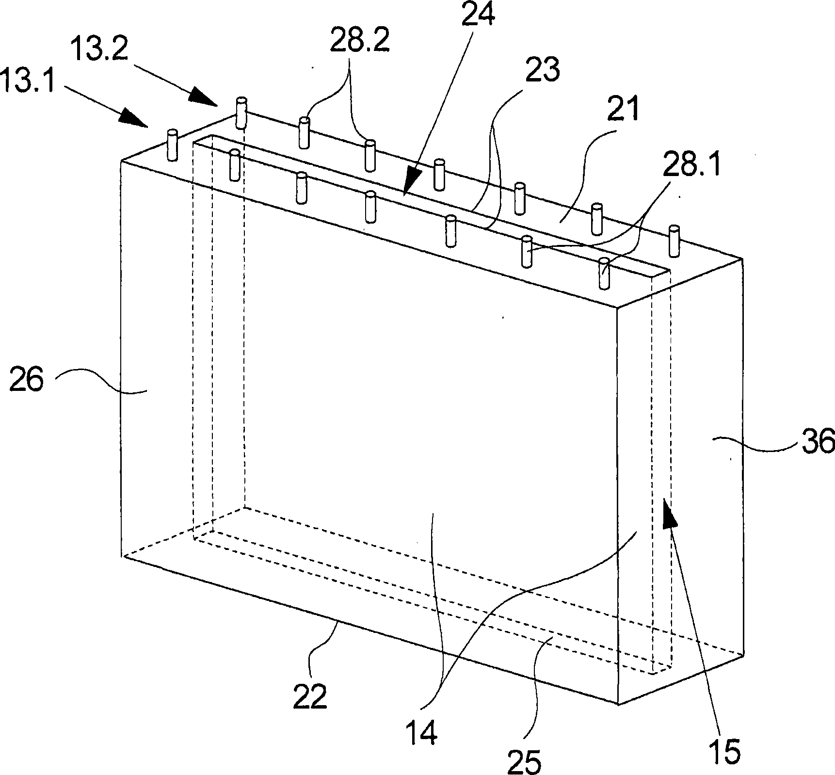
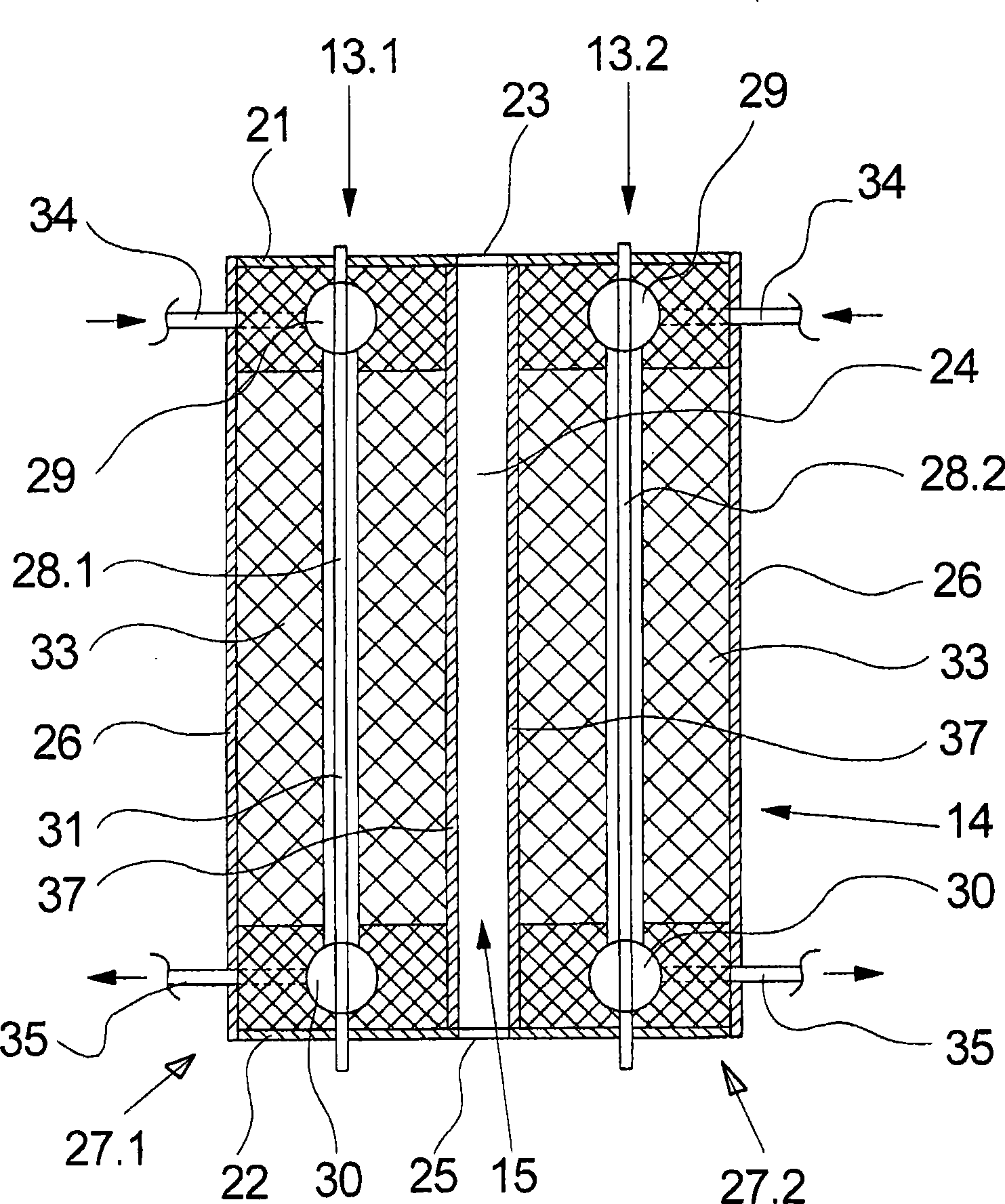
A texturing machine is described for texturing and reeling a plurality of threads which is composed of two machine halves. The machine halves are placed against one another in a mirror-image manner and have respectively several operating points with several process units for texturing and reeling several threads. Heating devices thereby face one another in a symmetry plane, which heating devices can be controlled and regulated separately from one another in the machine halves. In order to obtain a compact, space-saving construction and also avoid heat losses, the heating devices of the two machine halves are arranged jointly in the symmetry plane in an insulating housing according to the invention, a heat barrier being embodied inside the insulating housing between the heating devices. Individual settings in the heating devices are thus possible without impacting one another.

Description

technical field [0001] The invention relates to a texturing machine for texturing and winding a large number of filaments according to the preamble of claim 1 . Background technique [0002] A texturing machine of this type is known from WO 98 / 33963. [0003] Known texturing machines have a large number of processing stations in order to simultaneously texturize and wind a large number of filaments into bobbins. Here, working units such as feeding unit, heating unit, cooling unit, texturing unit and winding unit are held in a frame. For this purpose, the individual processing stations and thus the working group are divided into two machine halves, wherein the machine halves are arranged mirror-images of each other. This configuration achieves a relatively high space utilization in order to obtain an advantageous ratio between the number of processing stations and the space requirement of the machine. In this case, the individual processing stations can be operated indepen...

Claims


Application Information

Patent Timeline
Patent Type & Authority Applications(China)
IPC IPC(8): D02G1/02
CPCD02G1/0266
Inventor M·菲舍尔T·沃特曼M·赫茨贝格
Owner OERLIKON TEXTILE GMBH & CO KG
Learn More