
Body pressing device for transformer

A compression device and transformer technology, applied in the direction of transformer/inductor coil/winding/connection, inductance/transformer/magnet manufacturing, electrical components, etc., can solve the problems of transformer coil deformation, transformer accidents, elastic buffering of the device body, etc. , to save maintenance costs, protect safety, and reduce costs

Inactive Publication Date: 2011-05-04
WOLONG ELECTRIC GRP CO LTD +1
View PDF4 Cites 0 Cited by
  • Summary
  • Abstract
  • Description
  • Claims
  • Application Information

AI Technical Summary

Problems solved by technology

This compression or tension method cannot elastically cushion the body of the transformer when a short circuit occurs in the transformer, and it is easy to cause deformation of the transformer coil, thereby causing an accident in the transformer.

Method used


Image

  • Body pressing device for transformer
  • Body pressing device for transformer

Examples


Embodiment Construction

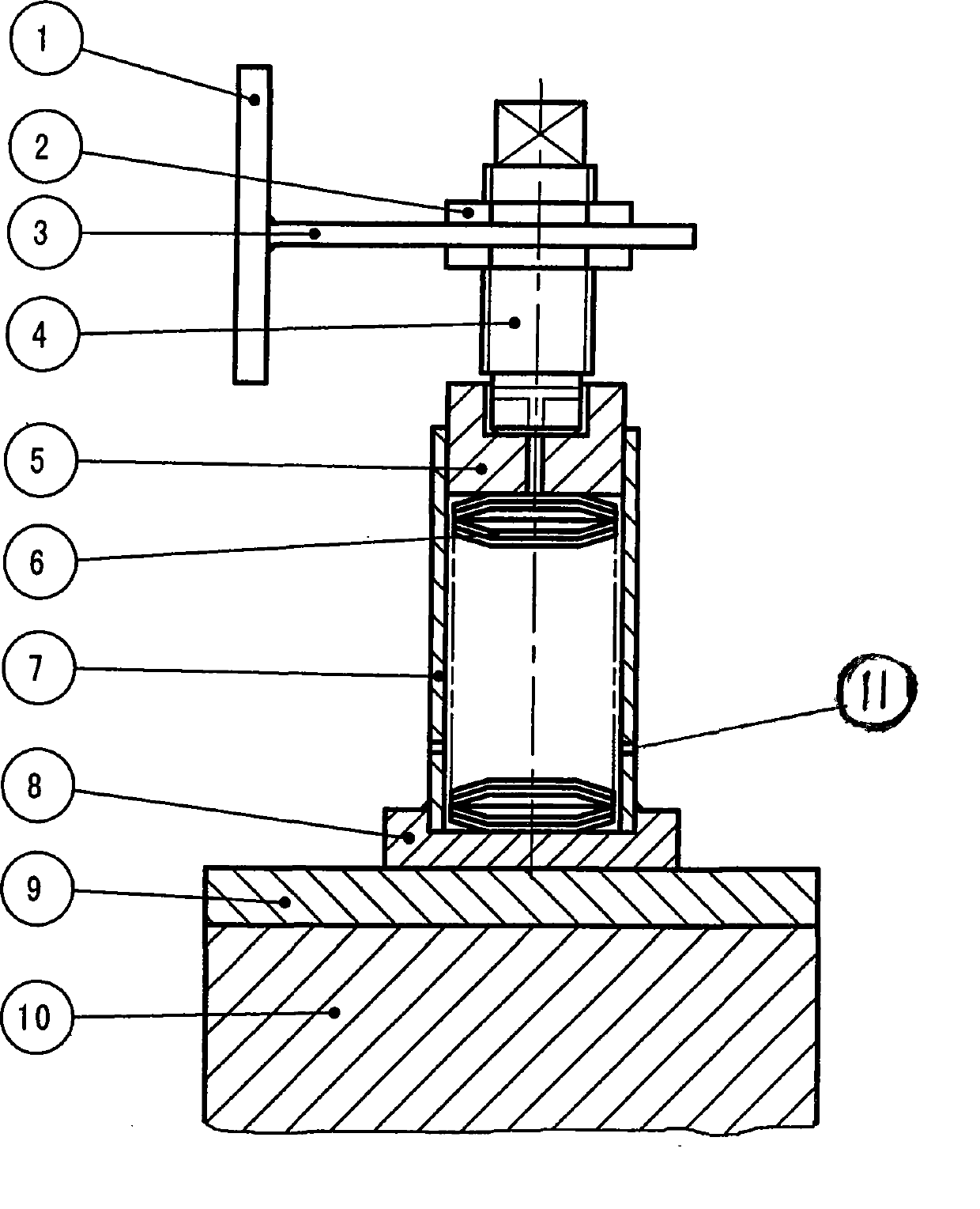
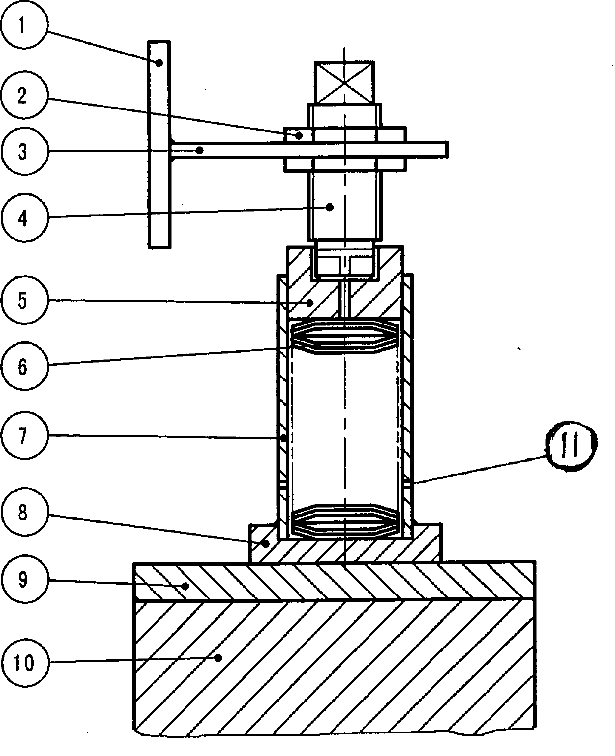
[0009] The present invention mainly consists of the coil pressing plate 9 placed on the upper part of the coil 10 and the iron core upper clamp 1, the washer 8 placed on the coil pressing plate 9 with the briquetting sleeve 7, the butterfly spring 6 and the pressing piece placed in the briquetting sleeve 7. Block 5, which is placed on the top of the pressing block 5 and consists of a compression screw 4 with a nut 2 and a connector 3; one end of the connector 3 is welded and fixed on the iron core upper clamp 1.

[0010] After the transformer is assembled, use a wrench to rotate the compression screw 4, so that the compression screw 4 and the compression block 5 move downward, adjust the compression degree with the coil pressure plate 9, and then use the wrench to tighten the two compression nuts 2 The compression screw 4 is locked on the upper and lower sides of the connecting plate 3 to prevent the compression screw 4 from loosening due to vibration during transportation and ...


PUM


Abstract

A body holding apparatus of a transformer belongs to the manufacturing technical field of matching accessories of transformers. The body holding apparatus mainly comprises a coil pressure plate (9) and an iron core upper clamping piece (1) installed at the upper part of a coil (10), a washer (8) equipped with a lock block sheath (7) and installed on the coil pressure plate (9), a belleville spring (6) and a lock block (5) installed in the lock block sheath (7), and a compressing screw rod (4) equipped with a screw nut (2) and a connecting piece (3) and installed on the lock block (5). One endof the connecting piece (3) is fixedly welded with the iron core upper clamping piece (1). The body holding apparatus has the advantages of reasonable integral structure design, low cost and simple installment, and can overcome the defects that when the transformer is transported, the coil and the coil pressure plate separate from each other due to the shock caused in turning, sudden braking, bumping and normal and safe running of a transport vehicle, thereby ensuring that the coil pressure plate can stand a sustained pressure and the compactness of the structure of the body, and improving the transformer resistance to short-circuit.

Description

technical field [0001] The invention relates to a compacting device for a transformer body, which belongs to the technical field of manufacturing transformer accessories. Background technique [0002] The axial compression method of the existing transformer body mainly relies on steel pressing nails or by pulling the screw rod to compress the body. This pressing or tensioning method cannot elastically cushion the body of the transformer when a short circuit occurs in the transformer, and it is easy to cause deformation of the transformer coil, thereby causing an accident in the transformer. Contents of the invention [0003] The object of the present invention is to provide a compacting device for a transformer body which is reasonably designed and can effectively ensure the safe operation of the transformer. [0004] The present invention is a body pressing device for a transformer, which includes a coil pressing plate placed on the upper part of the coil and an upper ir...

Claims


Application Information

Patent Timeline
Patent Type & Authority Patents(China)
IPC IPC(8): H01F41/00H01F27/30
Inventor 马金山鲁玮马君张键王娥
Owner WOLONG ELECTRIC GRP CO LTD
Learn More