
Fault diagnosis method for turbine emergency protection device

A protection device and fault diagnosis technology, which is applied to emergency protection circuit devices, measuring devices, fault locations, etc., can solve problems such as system availability and reliability discounts, steam turbine units tripping incorrectly, failure to protect steam turbines, etc., to achieve reliability and Strong availability, full transparency of data, and elimination of potential failures

Active Publication Date: 2011-04-20
中创清洁能源发展(沈阳)股份有限公司
View PDF0 Cites 0 Cited by
  • Summary
  • Abstract
  • Description
  • Claims
  • Application Information

AI Technical Summary

Problems solved by technology

At present, although many systems at home and abroad use redundant PLC protection systems to effectively overcome the shortcomings of traditional protection systems, they are obviously insufficient in the continuous online diagnosis and online test functions of the control loop. At present, the more advanced online diagnosis method is through manual The oil pressure online test is to manually test the feedback oil pressure of the oil pressure test block to detect the availability of the ETS system. However, because it involves the steam turbine unit, it may cause false trips. Operators usually rarely operate this type of test. The availability of the system At the same time, because the target of the test is mainly locked on the electromagnetic slide valve, it is difficult to find potential failures in other links of the system such as control logic and partial short circuit of the electromagnetic coil in time, and the system does not meet the requirements of high reliability.
In addition, the current ETS system does not have a reliable fault self-diagnosis function, which means that if there is a problem with itself and it is not found, it will not be able to protect the steam turbine.

Method used


Image

  • Fault diagnosis method for turbine emergency protection device
  • Fault diagnosis method for turbine emergency protection device

Examples


Embodiment Construction

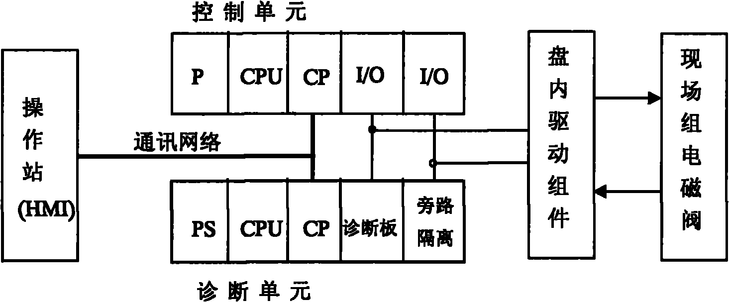
[0017] Hardware system: such as figure 1 The system shown is composed of a human-machine interface unit (HMI), a protection program control unit, a bypass isolation unit, a continuous diagnosis unit, and a test valve block.

[0018] Monitoring operation: The operating station (HMI) can realize continuous monitoring of the main steam valve, non-return valve, quick-closing valve circuit status circuit, fault monitoring and alarm of the controller and template, online diagnosis and system configuration programming.

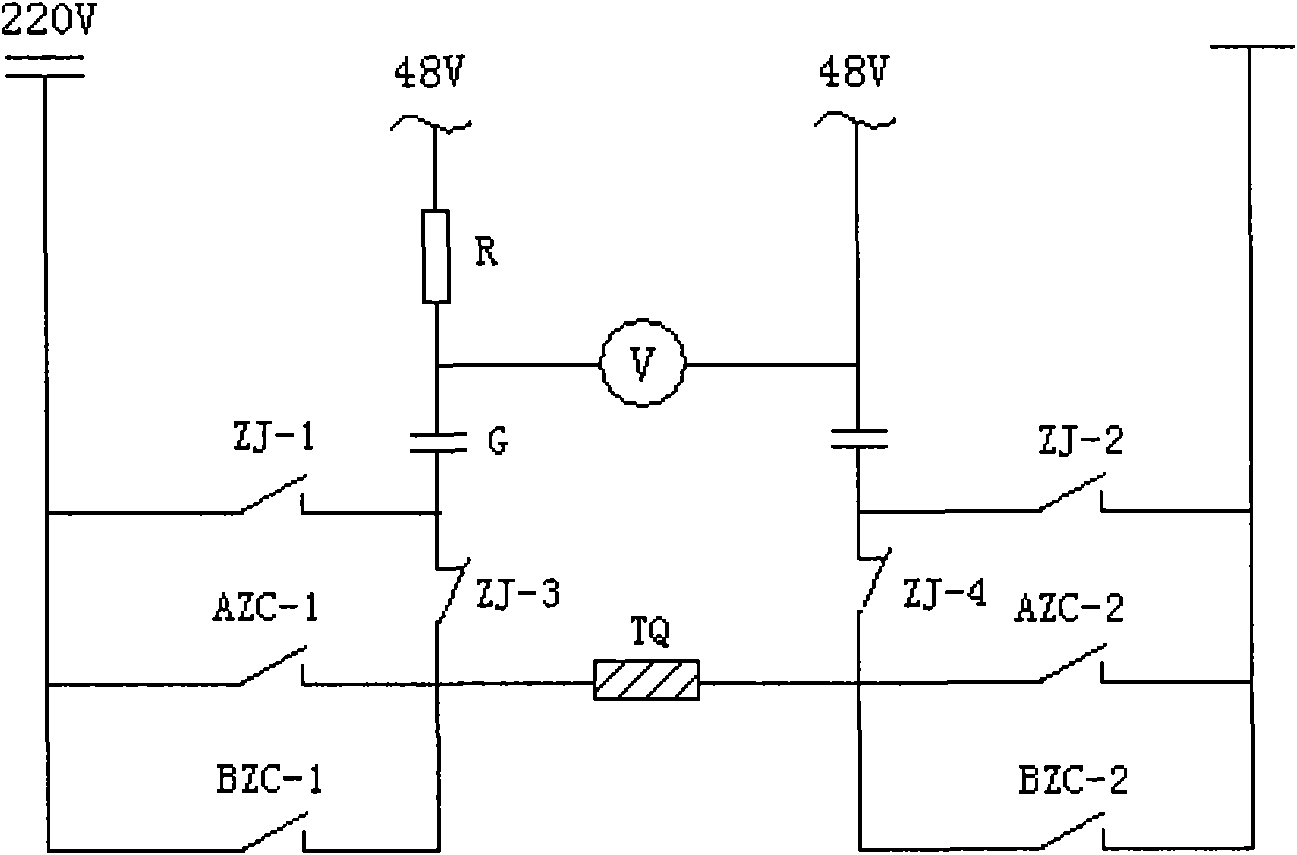
[0019] Continuous diagnosis: if figure 2 As shown in the figure: 220V: protection drive circuit power supply;

[0020] ~48V: diagnostic test voltage (AC); Voltage measuring transmitter;

[0021] AZC, BZC: Action contactor (relay) driven by A and B controllers;

[0022] ZJ-1~4: Continuous measurement / online test switching relay; TQ: Electromagnetic action coil (magnetic force circuit breaker accelerator coil, etc.). Under the normal operating state of the unit,...


PUM


Abstract

The invention discloses a fault diagnosis method for an emergency protection device of a steam turbine, and relates to a comprehensive fault diagnosis system with real-time closed-loop continuous diagnosis function. The system adopts a method for analyzing the deviation between a voltage testing curve combining an electric measuring signal of analog quantity and a signal of oil pressure switch quantity and a standard signal curve to judge the state of a protective closed-loop circuit and usability of the system, wherein the system isolates and prevents the exciting current from impacting a test loop and causes the fault of the test loop through the control of strong current and weak current of the circuit; and the system finds the abnormality in the circuit through the uninterrupted loading of low-level testing voltage and the receiving of a testing signal fed back by the current. A fault point of the system is judged through deviation between the feedback signal and a loading curve and a standard signal-level loading curve. The method can realize the real-time detection of fault of a controller system, fault of a communication network, earthed short circuit / open circuit of a field cable, short circuit / open circuit / local short circuit of an electromagnetic coil and the in-time detection of the fault of a drive relay and an oil pressure slide valve, thereby substantially improving usability and reliability of the ETS system.

Description

technical field [0001] The invention relates to a fault diagnosis system for an emergency protection device of a steam turbine generator set in a thermal power plant, in particular to a comprehensive fault diagnosis system with a real-time closed-loop continuous diagnosis function. Background technique [0002] The function of the emergency protection control system (ETS) of the steam turbine generator set in a thermal power plant is to realize the safety shutdown protection according to the preset procedure when the steam turbine fails seriously, so as to prevent the occurrence of major accidents and ensure the safety of the unit and personnel. [0003] The ETS system entered the domestic market along with the technology introduction of large-scale power generation equipment. At present, although many systems at home and abroad use redundant PLC protection systems to effectively overcome the shortcomings of traditional protection systems, they are obviously insufficient in ...

Claims


Application Information

Patent Timeline
Patent Type & Authority Patents(China)
IPC IPC(8): G01D21/02G01R31/02G01R31/08H02H7/06G01M99/00
Inventor 宗学军杨忠君陈斌杨辉志
Owner 中创清洁能源发展(沈阳)股份有限公司
Learn More