
Intelligent ash blowing control system based on sound wave gas temperature field measuring technique

A gas temperature and control system technology, applied in the direction of solid residue removal, combustion product treatment, combustion methods, etc., can solve the problems that the smoke temperature cannot be monitored in real time, and the thermocouple cannot work normally for a long time, so as to achieve broad development and The effect of applying the foreground

Inactive Publication Date: 2009-07-08
陕西午禾科技有限责任公司
View PDF0 Cites 9 Cited by
  • Summary
  • Abstract
  • Description
  • Claims
  • Application Information

AI Technical Summary

Problems solved by technology

In the prior art, there are also some enterprises that use means such as thermocouples or infrared radiation combined with BP algorithm, RPROP algorithm, etc. to realize online monitoring and calculation of the real-time flue gas temperature inside the boiler. Smoke temperature measurement points, other places such as the furnace outlet, high temperature convection area, etc., due to the harsh working environment, the thermocouples arranged in this area cannot work normally for a long time, so the smoke temperature in these parts cannot be monitored in real time

Method used


Image

  • Intelligent ash blowing control system based on sound wave gas temperature field measuring technique
  • Intelligent ash blowing control system based on sound wave gas temperature field measuring technique
  • Intelligent ash blowing control system based on sound wave gas temperature field measuring technique

Examples


Embodiment Construction

[0083] The content of the present invention will be further described below in conjunction with the accompanying drawings, but the actual production structure of the present invention is not limited to the illustrated embodiment.

[0084] The hardware structure of the intelligent soot blowing control system of the present invention is as follows: figure 1 As shown, it consists of a plurality of sound wave emission / reception sensors 1 arranged at corresponding positions around the heating surface of the boiler, and a plurality of preamplifier boxes 2 and process control units ( Composed of PCU) 3, intelligent soot blowing controller 4 and industrial computer 5, the preamplifier box 2 is connected to the process control unit 3 through a cable, and the current signal output terminal of the process control unit 3 is connected to the corresponding input terminal of the intelligent soot blowing controller 4 , the monitoring data signal output end of the process control unit 3 is co...


PUM


Abstract

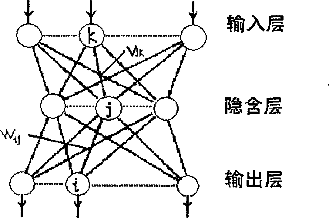
The invention relates to an intelligent soot-blowing control system on the basis of a sound wave gas temperature field measuring technique, which consists of a plurality of sound wave transmitting / receiving sensors arranged on the peripheral side of a heating surface of a thermal power generating unit boiler, preamplifier boxes correspondingly connected with each sound wave transmitting / receiving sensor, a process control unit (PCU), an intelligent soot-blowing controller and an industrial computer, wherein the amplifying signal output end of the preamplifier box is connected to the process control unit, the output end of the process control unit is connected with the corresponding input ends of the intelligent soot-blowing controller and the industrial computer, and the output end of the intelligent soot-blowing controller is externally connected to a DCS control system which guides the work of a boiler soot blower. The industrial computer is loaded with a software system on the basis of a wavelet neural network computational method, computes and processes data signals entering the intelligent soot-blowing controller through the software system, and then transmits soot-blowing optimization guidance information to the DCS control system so as to optimize and guide the boiler soot blower to blow soot as required.

Description

technical field [0001] The content of the invention belongs to the technical field of intelligent control systems for combustion equipment, and relates to an intelligent soot blowing control system for effectively removing ash deposits on convective heating surfaces of boilers of thermal power plants in thermal power plants. Background technique [0002] During the working process of the thermal power unit boiler, when the boiler burns solid fuel (such as coal, etc.) or liquid fuel containing ash, a large amount of fly ash is formed because the combustion product contains ash particles, sulfur oxide and other substances, such as a 300MW The amount of fly ash in the boiler per day and night can reach 700-1200t (depending on the ash content of the coal). After the fly ash flows through convective heating surfaces such as convective superheaters, reheaters, economizers, and water-cooled walls (four tubes) in the boiler, some of them are deposited on the heating surfaces in vari...

Claims


Application Information

Patent Timeline
IPC IPC(8): F23J3/00
Inventor 陈平安陈在维牛建设任悦
Owner 陕西午禾科技有限责任公司
Learn More