A marine vessel

A technology for water transportation and work, applied in the direction of transportation and packaging, propulsion components, gas/liquid distribution and storage, etc., can solve problems such as positioning problems

Active Publication Date: 2009-07-01
WARTSILA FINLAND OY
View PDF0 Cites 11 Cited by
  • Summary
  • Abstract
  • Description
  • Claims
  • Application Information

AI Technical Summary

Problems solved by technology

Positioning of such a tank or several tanks can be problematic since conventional tanks are large pressure vessels in which space utilization is critical when considering e.g. the economy and convenience of using the tank

Method used


Image

  • A marine vessel
  • A marine vessel
  • A marine vessel

Examples


Embodiment Construction

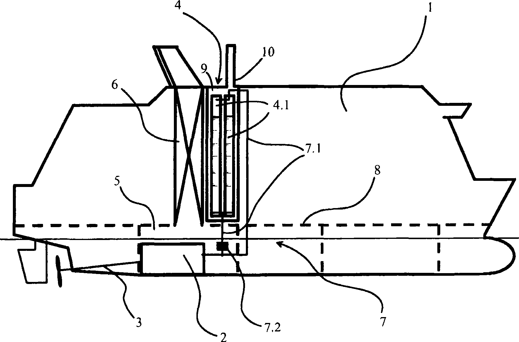
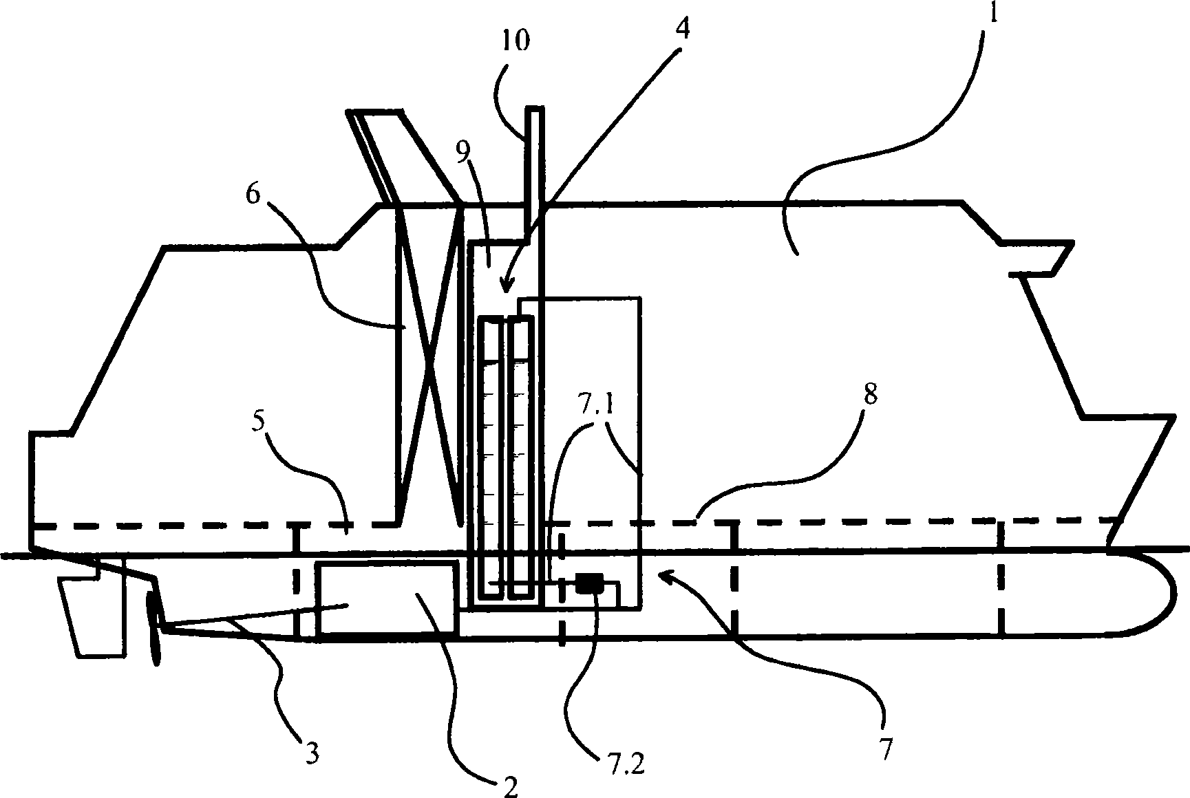
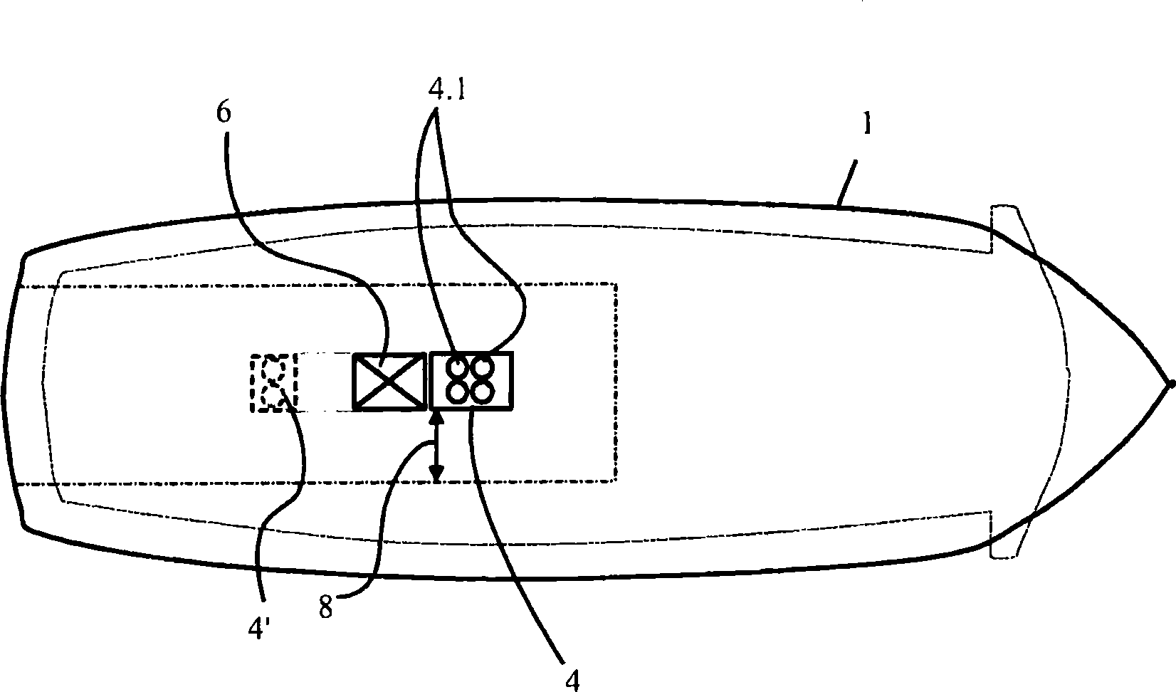
[0013] Such as figure 1 The watercraft 1 shown in is equipped with a main engine 2 that powers the propulsion system 3 of the watercraft. Obviously, the number and arrangement of engines installed may vary according to the type and size of the watercraft. The engine 2 operates on gaseous fuel, which is stored in the fuel tank means 4 in liquid phase, which in practice means that the temperature of the gas is typically about minus 162°C. The engine 2 is installed in an engine compartment 5 . The nacelle is equipped with a nacelle casing 6 extending from the nacelle to the outside of the watercraft 1 , through which eg an exhaust pipe of the engine can be laid. exist figure 1 In the embodiment shown, the fuel tank arrangement 4 is arranged in the vicinity of the longitudinally aligned nacelle casing above the bulkhead deck 8 . The fuel tank unit 4 is connected to the engine 2 via an air supply system 7 comprising the required piping 7.1 and an evaporator device 7.2 for evapo...


PUM


Abstract

A marine vessel (1) operated with gaseous fuel having at least one gas powered engine (2), which vessel is provided with a fuel tank arrangement (4) in which the fuel is stored in liquid phase, in which vessel the engine is positioned in an engine room which is provided with an engine room casing (6) extending from the engine room to exterior of the vessel, The fuel tank arrangement (4) is arranged in vicinity of the engine room casing.

Description

technical field [0001] The invention relates to a marine vehicle operating on gaseous fuel according to the preamble of claim 1, having at least one gas-powered engine, which marine vehicle is equipped with a fuel tank for storing fuel in liquid phase, in which The engine in the watercraft is placed in a nacelle equipped with a nacelle casing extending from the nacelle to the outside of the watercraft. Background technique [0002] Gas fuels are increasingly being used on various types of watercraft due to their clean combustion and availability compared to, for example, heavy fuel oil or marine diesel. [0003] Gases are generally stored in liquid phase in cryogenic fuel tanks, which are also pressure vessels. Positioning of such a tank or several tanks can be problematic since conventional tanks are large pressure vessels in which space utilization is critical when considering e.g. the economy and convenience of using the tank . Compared with diesel fuel tanks, LPG tank...

Claims


Application Information

Patent Timeline
Patent Type & Authority Applications(China)
IPC IPC(8): B63B25/16F17C13/08B63H21/14
CPCF17C2223/0161F17C2223/033B63H21/14B63B2770/00F17C2265/066F17C2265/03F17C3/00F17C2221/033F17C2201/0138F17C2270/0105F17C2201/054B63B25/16Y02T70/5218F17C2227/0393F17C2201/032B63B17/0027B63H21/38B63B17/0036B63H21/32B63B25/12F17C2201/01
Inventor S·汉努拉O·勒范德T·斯皮拉K·詹森P·马蒂凯恩
Owner WARTSILA FINLAND OY
Why Eureka
Try Eureka