
Non-impeller hollow screw axis centrifugal cavity pump

A technology with a hollow shaft and no impeller, applied in the field of centrifugal pumps, can solve problems such as low efficiency, complex structure, and many consumables, and achieve the effects of improved efficiency, high-quality materials, and low maintenance

Active Publication Date: 2009-06-24
大连恒基新润水务有限公司
View PDF0 Cites 2 Cited by
  • Summary
  • Abstract
  • Description
  • Claims
  • Application Information

AI Technical Summary

Problems solved by technology

[0009] The purpose of the present invention is to provide a hollow screw-shaft centrifugal pump without impeller with simple structure, less consumables, less energy consumption and no leakage in view of the current common liquid pumps that have complex structures, many consumables, high energy consumption, and low efficiency. cavity pump

Method used


Image

  • Non-impeller hollow screw axis centrifugal cavity pump
  • Non-impeller hollow screw axis centrifugal cavity pump

Examples


Embodiment

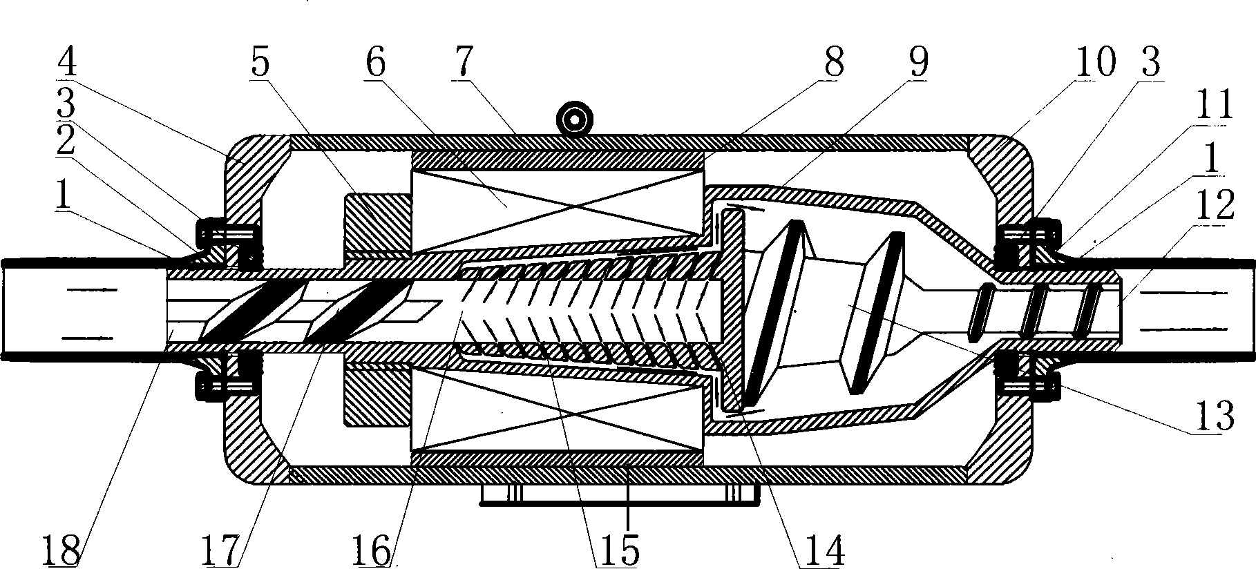
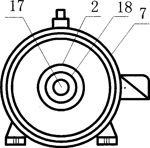
[0031] An impellerless hollow screw shaft centrifugal cavity pump, comprising a housing 7, a conical hollow shaft 9, a front helical guide body 17, a rear helical guide body 13, a water inlet pipe 2, a water outlet pipe 11, and a cavity cone 14 , the front end cover 4, the rear end cover 10, the rotor 6; the two ends of the housing 7 are respectively provided with front and rear end covers 4 and 10, and the centers of the front and rear end covers 4 and 10 are respectively provided with a central hole, and the center A bearing 3 is installed in the hole, and the front and rear end covers 4 and 10 are fixedly connected with the water inlet interface pipe 2 and the water outlet interface pipe 11 respectively by screws.

[0032] The shell 7 is equipped with a tapered hollow shaft 9, the two ends of the tapered hollow shaft 9 are respectively provided with a water inlet 18 and a water outlet 12, and the two ends of the tapered hollow shaft 9 are respectively provided with a sealing...


PUM


Abstract

The invention relates to a hollow spiral shaft eccentric cavity pump without a vane wheel. A front spiral diversion body and a rear spiral diversion body are arranged in a conical hollow shaft provided with a water inlet and a water outlet and are respectively fixedly connected with the inner wall of the conical hollow shaft; the front end of the rear spiral diversion body is provided with a cavity conical body, and the front end of the cavity conical body is fixedly connected with the inner wall of the conical hollow shaft; and the wall of the cavity conical body is provided with a plurality of apopores. A rotor sleeve is arranged outside the conical hollow shaft, a rotor is arranged in the housing sheathed on the conical hollow shaft, and both ends of the conical hollow shaft are supported by bearings. The pump of the invention has the advantages of scientific and reasonable integral design, simple structure, convenient production, low material consumption, high material quality, low cost, easy assembly and disassembly, low daily maintenance, stable and reliable performance, energy saving and high efficiency and practicability. The pump of the invention is applicable to families, factories and mines, enterprises and institutions, agricultural irrigation, running water and other relative work units.

Description

technical field [0001] The invention relates to a centrifugal pump, in particular to a conical hollow screw shaft centrifugal cavity pump without an impeller. Background technique [0002] With the continuous development of science and technology, the application of liquid transmission technology is becoming more and more extensive. As the core liquid pump of the liquid transmission mechanism, it is extremely important and has reached the point where it cannot be abandoned. At present, there are many kinds and forms of liquid pumps, which can be used in different environments and show their different advantages and performances. However, in summary, the commonly used liquid pumps generally have the following common problems: [0003] 1. Large energy consumption: Commonly used liquid pumps are driven by a motor to rotate the pump shaft and impeller. Undoubtedly, the rotational torque is large. The impeller rotates in water with high resistance and large negative angle compone...

Claims


Application Information

Patent Timeline
Patent Type & Authority Applications(China)
IPC IPC(8): F04D1/04F04D29/42F04D29/44F04D29/22F04D29/046F04D29/12
Inventor 罗振芳王波俊王承河
Owner 大连恒基新润水务有限公司
Learn More