Control circuit for intelligent electric vehicle controller

A smart electric vehicle and control circuit technology, applied in the direction of electric vehicles, control drives, vehicle components, etc., can solve the problems of accurate detection of controller output current, increased circuit stress, and reduced power supply reliability, etc., to overcome tailing and The drift of the current limit point is too large, the output of the controller is stable, and the effect of improving reliability

Inactive Publication Date: 2009-06-17
TIANJIN SONGZHENG ELECTRONICS
View PDF0 Cites 12 Cited by
  • Summary
  • Abstract
  • Description
  • Claims
  • Application Information

AI Technical Summary

Problems solved by technology

[0003] 1. Since there is no accurate detection of the output current of the controller, it is impossible to intelligently control the output current of the controller when the motor is overloaded;
[0004] 2. Since there is no accurate linkage detection of Hall sensor signal and power tube on-off voltage drop, it is impossible to realize the dynamic judgment and protection of power tube breakdown and handlebar failure resulting in speeding;
[0005] 3. It is impossible to realize the protection of automatically cutting off the controller output after the embedded controller MCU crashes or is abnormally damaged
[0006] 4. Since there is no over-current protection circuit, when the power supply is in an over-current or short-circuit state, the delay of the control circuit causes the output current to increase continuously with the decrease of the output voltage during over-current, forming a tailing phenomenon, which increases the stress on the circuit , reducing the reliability of the power

Method used


Image

  • Control circuit for intelligent electric vehicle controller
  • Control circuit for intelligent electric vehicle controller
  • Control circuit for intelligent electric vehicle controller

Examples


Embodiment Construction

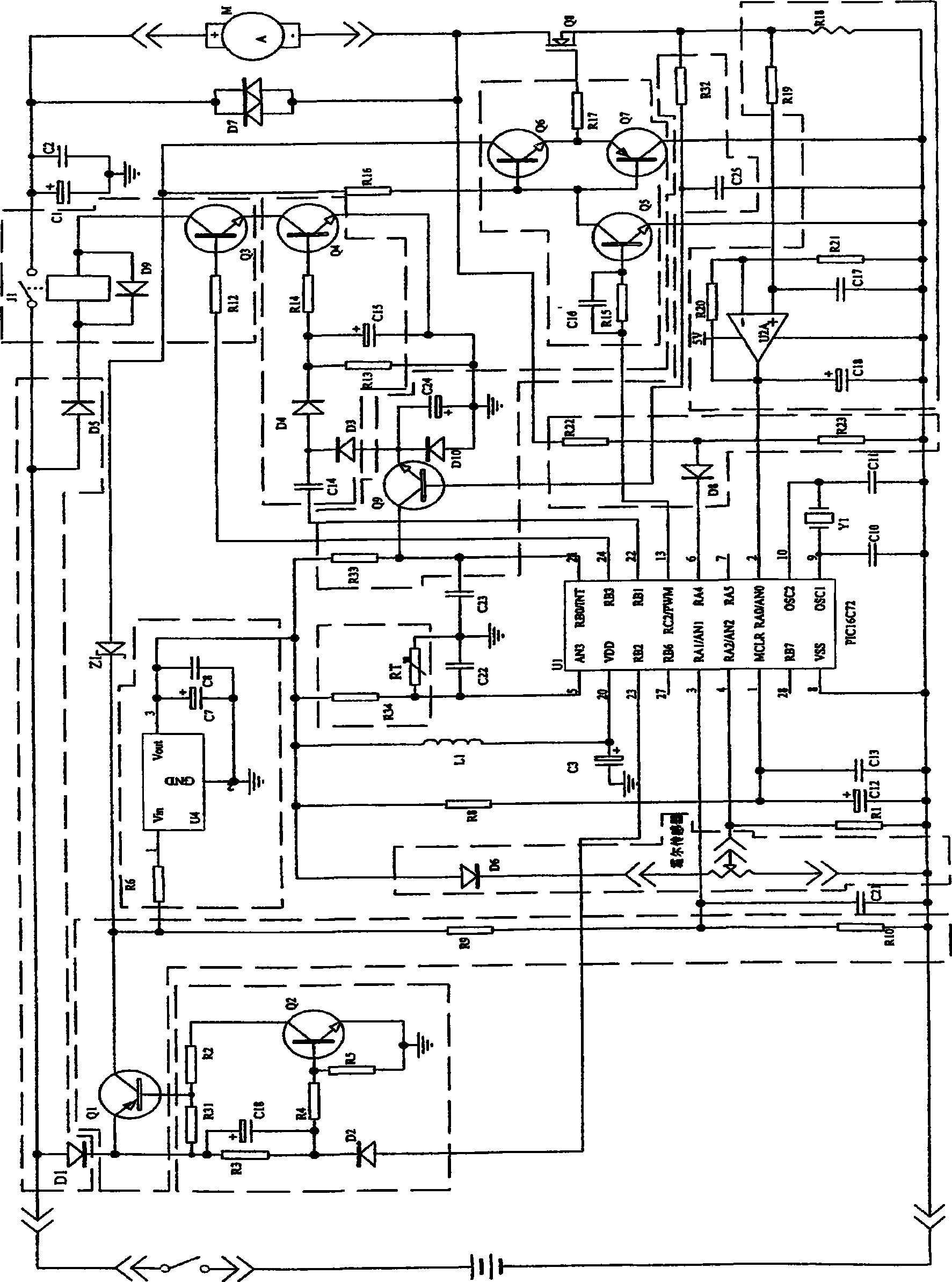
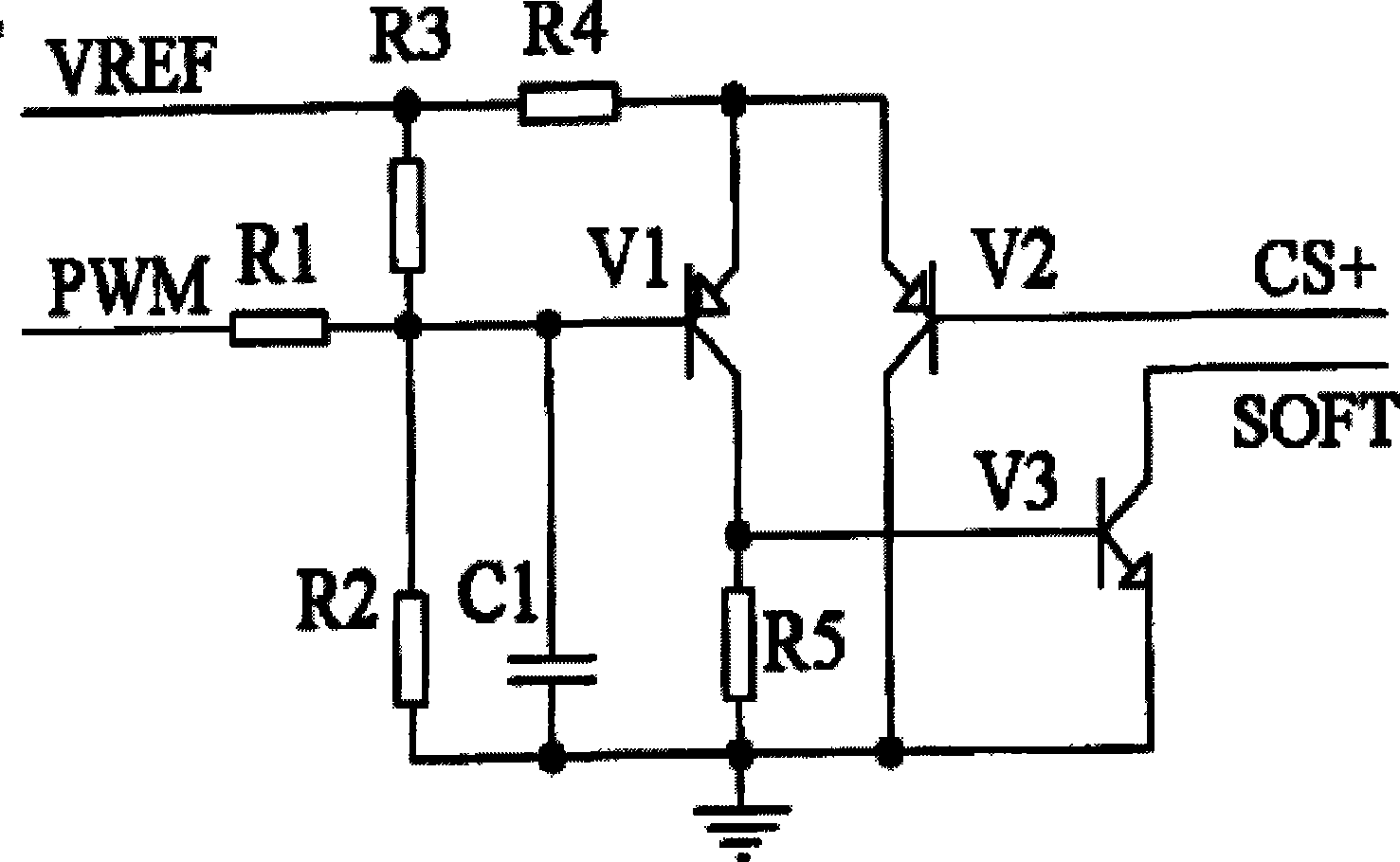
[0020] The technical solutions of the present invention will be described in detail below in conjunction with the specific circuit diagrams given in the accompanying drawings.

[0021] See Figure 1, 2, 3

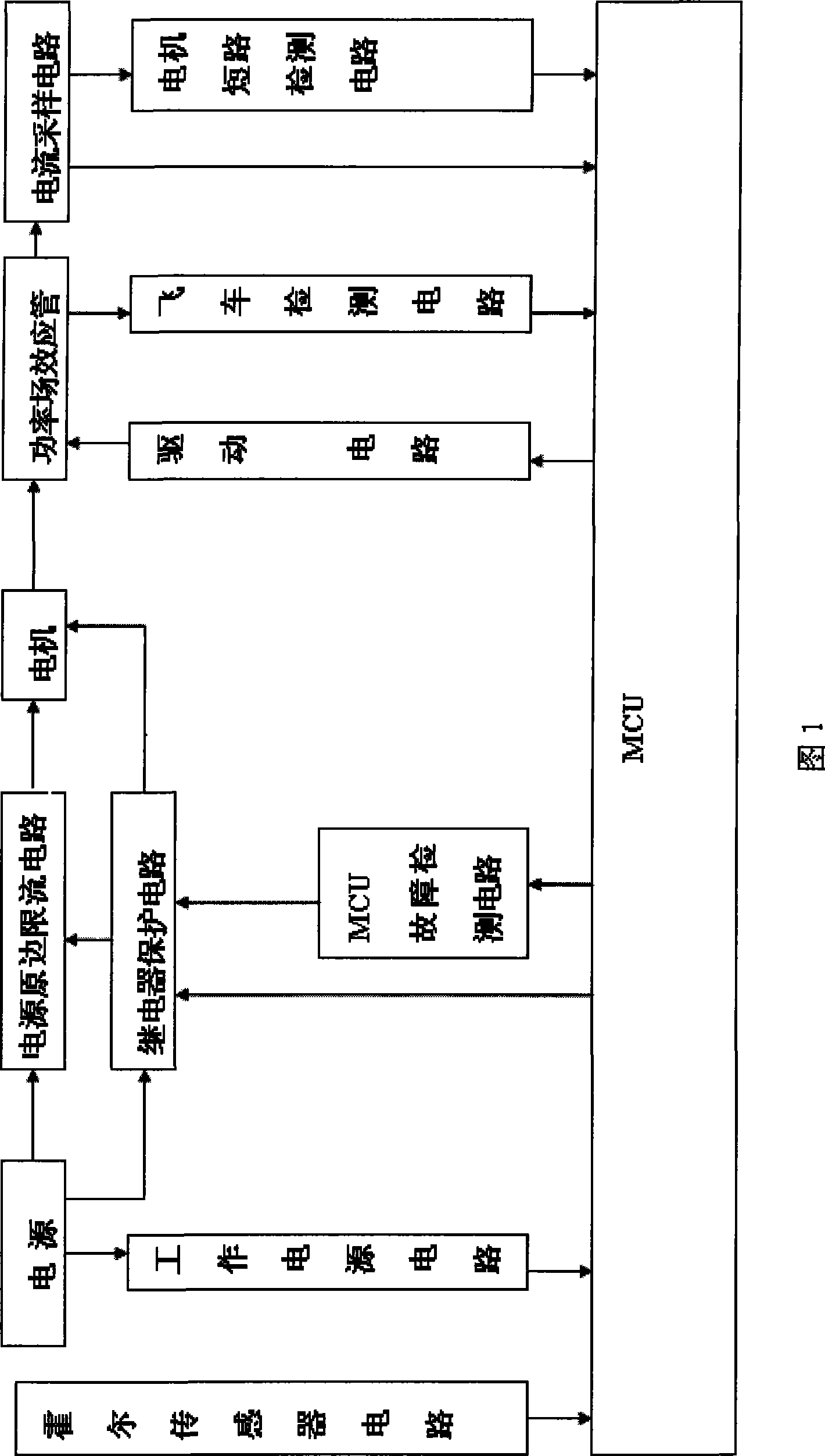
[0022] The present invention includes a power supply, a current limiting circuit on the primary side of the power supply, a relay protection circuit, a motor M and a power field effect transistor Q8, an embedded controller MCU controls a drive circuit and drives the power field effect transistor Q8, a Hall sensor circuit and all The embedded controller is directly connected, a power supply voltage detection circuit and a working power circuit are respectively connected between the power supply and the embedded controller MCU, and the embedded controller MCU fault detection circuit is connected between the relay protection circuit and the embedded Between the type controller MCU, a flying car detection circuit is connected between the field effect transistor and the embedded ...


PUM


Abstract

The invention discloses a control circuit of a controller of an intelligent electric vehicle, which comprises a power supply, a microprocessor, a circuit of a Hall sensor, a power field-effect transistor, a driving circuit, a circuit of a work power supply, a relay protection circuit, a current sampling circuit, a fault detecting circuit and an original edge current-limiting circuit of the power supply, wherein the power supply, the relay protection circuit, a motor, the field-effect transistor and the current sampling circuit are connected sequentially; the circuit of the work power supply is connected with the power supply; the driving circuit is connected with the microprocessor and the field-effect transistor respectively; the microprocessor controls to drive the conduction of the field-effect transistor, so as to control the conduction of the whole loop; the circuit of the Hall sensor, the relay protection circuit and the current sampling circuit are connected with the microprocessor respectively; the fault detecting circuit detects whether all the circuits work normally or not; the fault detecting circuit is connected with the microprocessor directly; and the original edge current-limiting circuit of the power supply is connected with the power supply, the motor and the relay protection circuit respectively and directly. The control circuit has the advantages of stable performance, high security and precise control.

Description

technical field [0001] The invention relates to a control circuit, in particular to a controller control circuit for an intelligent electric vehicle. Background technique [0002] Today, urban life is getting faster and faster, and the pursuit of efficiency has become the requirement of the general public. In terms of transportation, electric vehicles have the characteristics of energy saving, environmental protection, convenient and practical operation, and are accepted by consumers. Due to defects such as shortened mileage and poor climbing ability, the electric vehicle controllers in the prior art lack necessary detection circuits and overcurrent protection circuits, so good protection for electric vehicles cannot be achieved. Its existing defects are as follows: [0003] 1. Since there is no accurate detection of the output current of the controller, it is impossible to intelligently control the output current of the controller when the motor is overloaded; [0004] 2....

Claims


Application Information

Patent Timeline
IPC IPC(8): B60L15/00
Inventor 孔昭松
Owner TIANJIN SONGZHENG ELECTRONICS
Why Eureka
Try Eureka