
Ultrasonic wide-scene imaging method, device and system

A wide-view imaging and ultrasound technology, applied in image data processing, image data processing, instruments, etc., can solve the problems of large amount of calculation in 3D space search, insignificant increase in speed, deviation from correct position, etc., and achieve ideal stitching effect. Effect

Active Publication Date: 2009-06-17
SHENZHEN MINDRAY BIO MEDICAL ELECTRONICS CO LTD
View PDF0 Cites 29 Cited by
  • Summary
  • Abstract
  • Description
  • Claims
  • Application Information

AI Technical Summary

Problems solved by technology

The difference between the two is: the existing technical solution 3 has a process of using fuzzy logic to correct the local offset before starting the fitting, while the existing technical solution 2 does not have this process
[0015] Disadvantages of the existing technical scheme 1: the amount of calculation for three-dimensional space search is very large, which seriously affects the speed of wide-view imaging; and it is difficult to determine the rotation interval. If the interval is too small, the amount of calculation will be large, and if the interval is too large, the accuracy will be reduced. , since the exact angle is often between the two computed angles
[0016] Disadvantages of the existing technical solution 2: too much trust in the local offset, and the LSM calculation is performed directly without screening or correction; due to the noise of the ultrasonic image and the influence of tissue movement factors, it cannot be guaranteed that the offset calculated by all feature regions is uniform. Correct; if these offsets are used directly, the transformation parameters calculated by LSM may be inaccurate, resulting in abnormal results
[0017] Disadvantages of the third existing technical solution: the use of fuzzy logic to correct the local offset is reasonable; however, the formulation of fuzzy rules relies too much on experience, and it is difficult to guarantee universality
[0019] Disadvantages of the optimization scheme of the prior art scheme 2: the jump search is actually a sampling search with a sampling rate of m×n, where m and n are the jumping steps in the X direction and the Y direction respectively; the sampling search can increase the speed, but it must sacrifice Accuracy, even if you add another point-by-point search in the vicinity of the search results, the search may fail due to the excessive deviation of the starting position; if you set a smaller jump step size, you can reduce the chance of such errors, but At this time, the increase in speed is not obvious
[0020] Disadvantages of the optimization scheme of the prior art scheme 3: For a search area with a size of M×N, the rough search in the X direction can be regarded as a sampling search with a sampling rate of 1×N, and the rough search in the Y direction can be regarded as a sampling rate of 1×N. M×1 sampling search, therefore, this scheme will face the same problem as the optimization scheme of the existing technical scheme 2, that is, it is very likely that the result of the one-dimensional rough search has deviated from the correct position, and on this basis, the second dimensional exact search, the result is bound to fail
However, if a larger template size is set, it not only increases the amount of calculation, but also makes SAD more sensitive to the rotation angle.
However, the prior art solution 2 and the prior art solution 3 do not have the process of one-by-one rotation like the prior art solution 1. If they are sensitive to the angle, when the actual rotation angle is large, it is likely to cause a mismatch
[0022] In summary, the disadvantages of the prior art solution 1 are serious speed problems and accuracy problems when the rotation interval is not determined properly; the accuracy of the prior art solution 2 and the prior art solution 3 is not good, and must rely on the optimization scheme can solve the speed problem, but the accuracy of the optimization scheme is also questionable

Method used


Image

  • Ultrasonic wide-scene imaging method, device and system
  • Ultrasonic wide-scene imaging method, device and system
  • Ultrasonic wide-scene imaging method, device and system

Examples


Embodiment Construction

[0061] The ultrasonic wide-view imaging system of the present invention includes: a probe for transmitting ultrasonic waves to the object under test and receiving ultrasonic waves reflected from the object under test; a signal transceiver device connected with the probe for sending and receiving signals; a beamforming device connected with The signal transceiving device is connected to receive the echo signal; the signal processing device is connected to the signal transceiving device and used to process the signal output from the beamforming device; the image processing device is connected to the signal processing device for processing the image; and a display device connected to the image processing device for displaying the image; wherein the image processing device includes the ultrasonic wide-view imaging device of the present invention. figure 1 is a block diagram of an ultrasonic wide-view imaging system according to an embodiment of the present invention. As shown in t...


PUM


Abstract

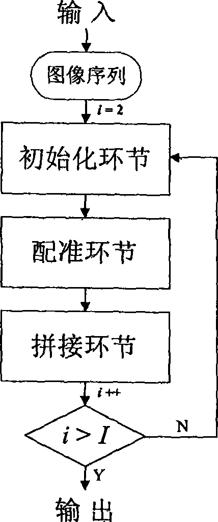
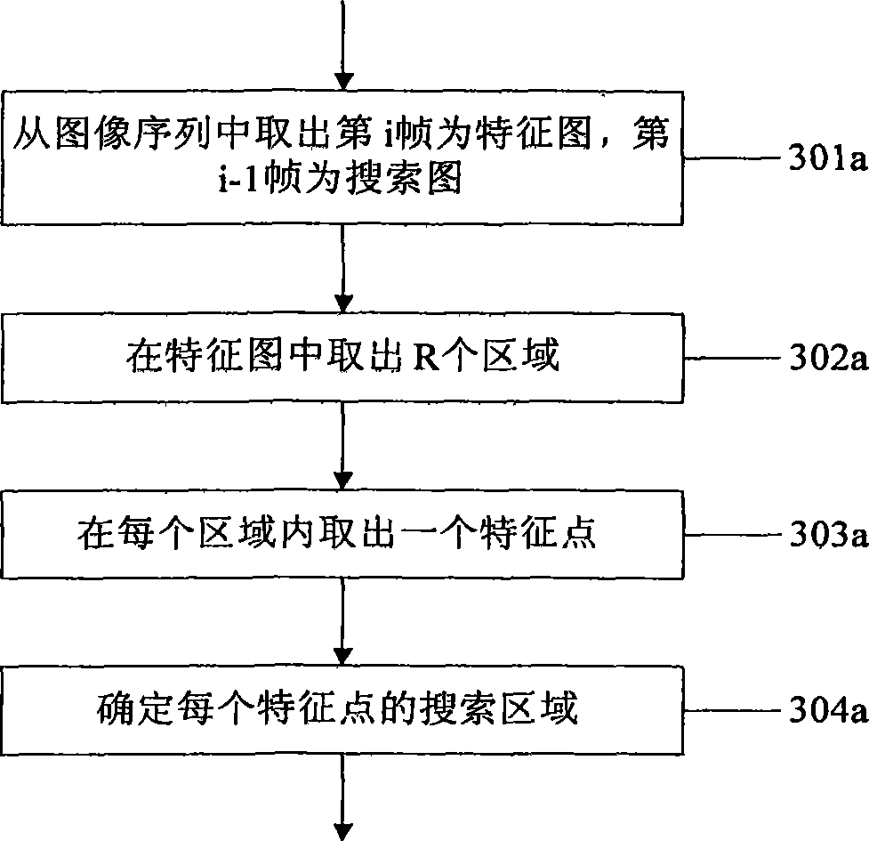
The present invention provides a panoramic ultrasound imaging method which comprises the following steps: (1) selecting a first image and a second image in a series of images, dividing each selected image into a plurality of areas; (2) selecting total or partial areas in the first image, and selecting a characteristic point in each of selected areas; (3) searching the matching point of each characteristic point selected in the step (2), modifying a transformation parameter along with processing of searching and feeding back the transformation parameter for the searching process; (4) confirming the transformation parameter when the searching is finished, and splicing the two images according to the transformation parameter; and (5) repeatedly executing the steps (1), (2), (3) and (4) until the series of images are spliced to an image. The invention also provides a panoramic ultrasound system which comprises the following components: a probe; a signal transceiver; a beam synthesizer; a signal processor; an image processor; and a display device, wherein the image processor comprises a device for executing the panoramic ultrasound imaging method according to the invention. The leading-out of feedback mechanism increases the searching accuracy.

Description

technical field [0001] The present invention generally relates to the field of ultrasonic imaging, in particular to a method, device and system for ultrasonic wide-view imaging. Background technique [0002] Panoramic imaging is an ultrasound imaging technology for the purpose of assisting medical diagnosis. Its advantage is that it is convenient for doctors to observe and measure diagnostic objects. [0003] Ultrasonic wide-view imaging technology is a technology that obtains a series of two-dimensional slice images by moving the probe in the same plane, and then stitches the series of two-dimensional images into a continuous slice image by using computer reconstruction methods. [0004] Ultrasound instruments are generally used by doctors to observe the internal tissue parts of the human body. By placing the probe on the corresponding skin surface of the human body, the doctor can obtain ultrasonic images of the part. Due to its non-invasiveness, convenience and reliabili...

Claims


Application Information

Patent Timeline
IPC IPC(8): A61B8/14G06T1/00
Inventor 田勇姚斌胡勤军
Owner SHENZHEN MINDRAY BIO MEDICAL ELECTRONICS CO LTD
Learn More