
Adjustment method of splicing type scanning imaging equipment and splicing type scanning imaging equipment

A scanning imaging device and scanning imaging technology, applied in image enhancement, image analysis, image communication, etc., can solve problems such as unfixed, splicing gaps or overlapping images, and spending a lot of time and energy

Inactive Publication Date: 2018-11-13
CHENGDU IDEALSEE TECH
View PDF3 Cites 8 Cited by
  • Summary
  • Abstract
  • Description
  • Claims
  • Application Information

AI Technical Summary

Problems solved by technology

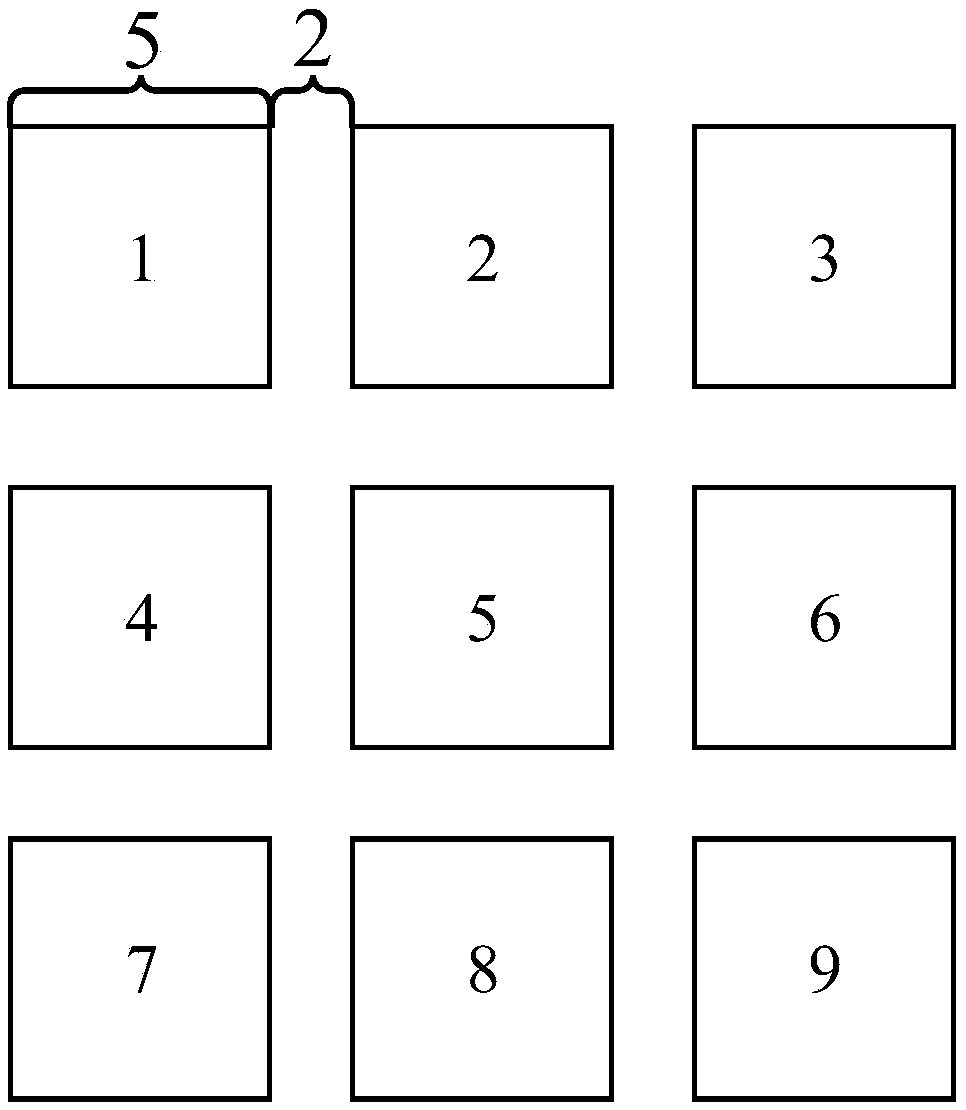
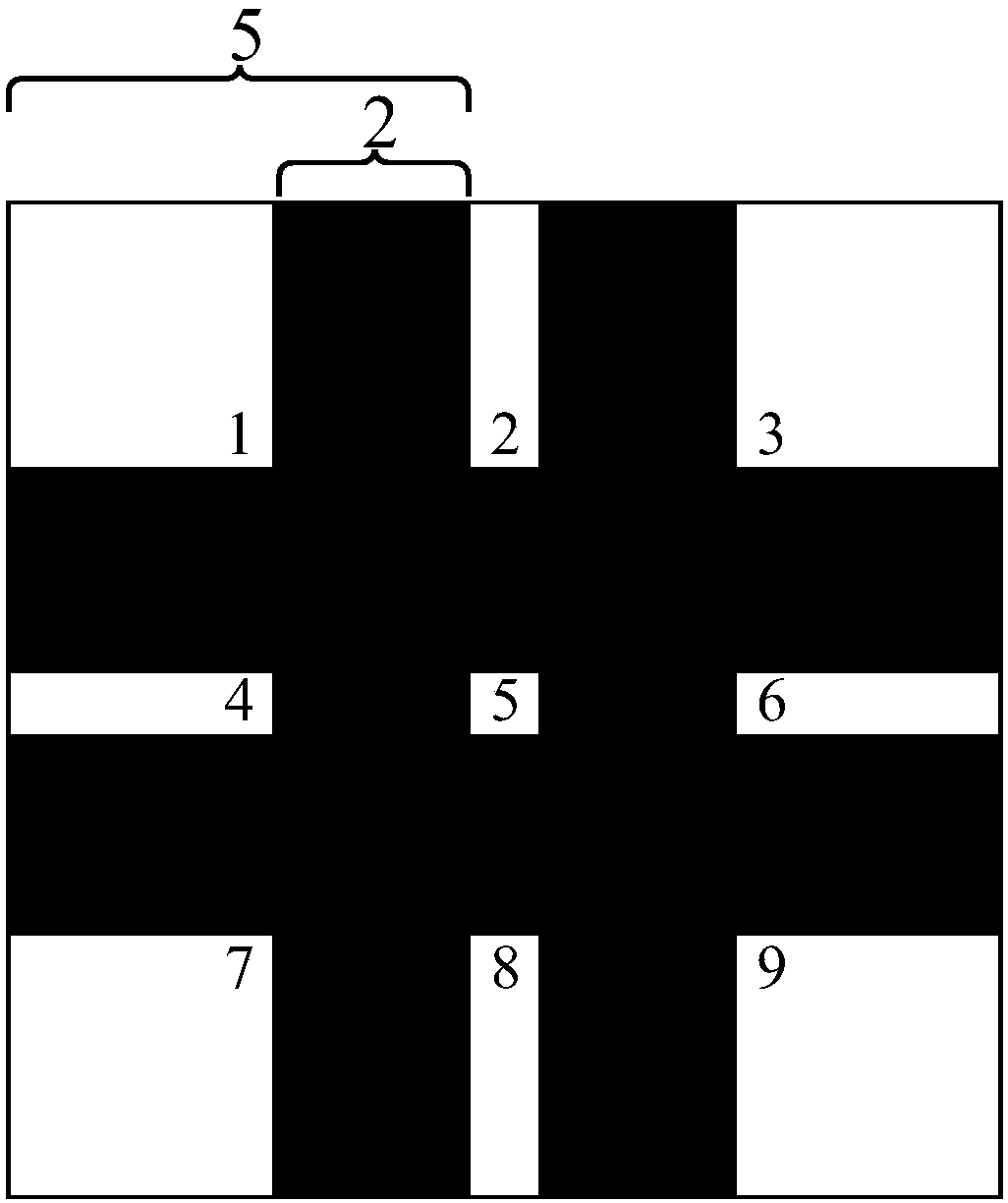
[0003] At present, in order to provide users with images of high resolution and large physical size, the images projected by multiple projectors are generally spliced ​​together. The distance between each projector and the projection screen will also change, and it is difficult to adjust to be consistent, so it will cause problems such as splicing gaps or image overlaps on the spliced ​​images on the projection screen. At this time, it is necessary to readjust each projection The position between the instruments and the projection parameters to reduce or eliminate stitching gaps or image overlapping problems require users to spend a lot of time and effort

Method used


Image

  • Adjustment method of splicing type scanning imaging equipment and splicing type scanning imaging equipment
  • Adjustment method of splicing type scanning imaging equipment and splicing type scanning imaging equipment
  • Adjustment method of splicing type scanning imaging equipment and splicing type scanning imaging equipment

Examples


Embodiment Construction

[0054] The following will clearly and completely describe the technical solutions in the embodiments of the present invention with reference to the accompanying drawings in the embodiments of the present invention. Obviously, the described embodiments are only some of the embodiments of the present invention, not all of them. Based on the embodiments of the present invention, all other embodiments obtained by persons of ordinary skill in the art without creative efforts fall within the protection scope of the present invention.

[0055] Embodiments of the present invention provide an adjustment method for a spliced ​​scanning imaging device and the spliced ​​scanning imaging device, which are used to conveniently adjust the position of a projected image, reducing the time and effort required by the user.

[0056] The first aspect of the embodiments of the present invention provides an adjustment method for spliced ​​scanning imaging equipment, the spliced ​​scanning imaging equ...


PUM


Abstract

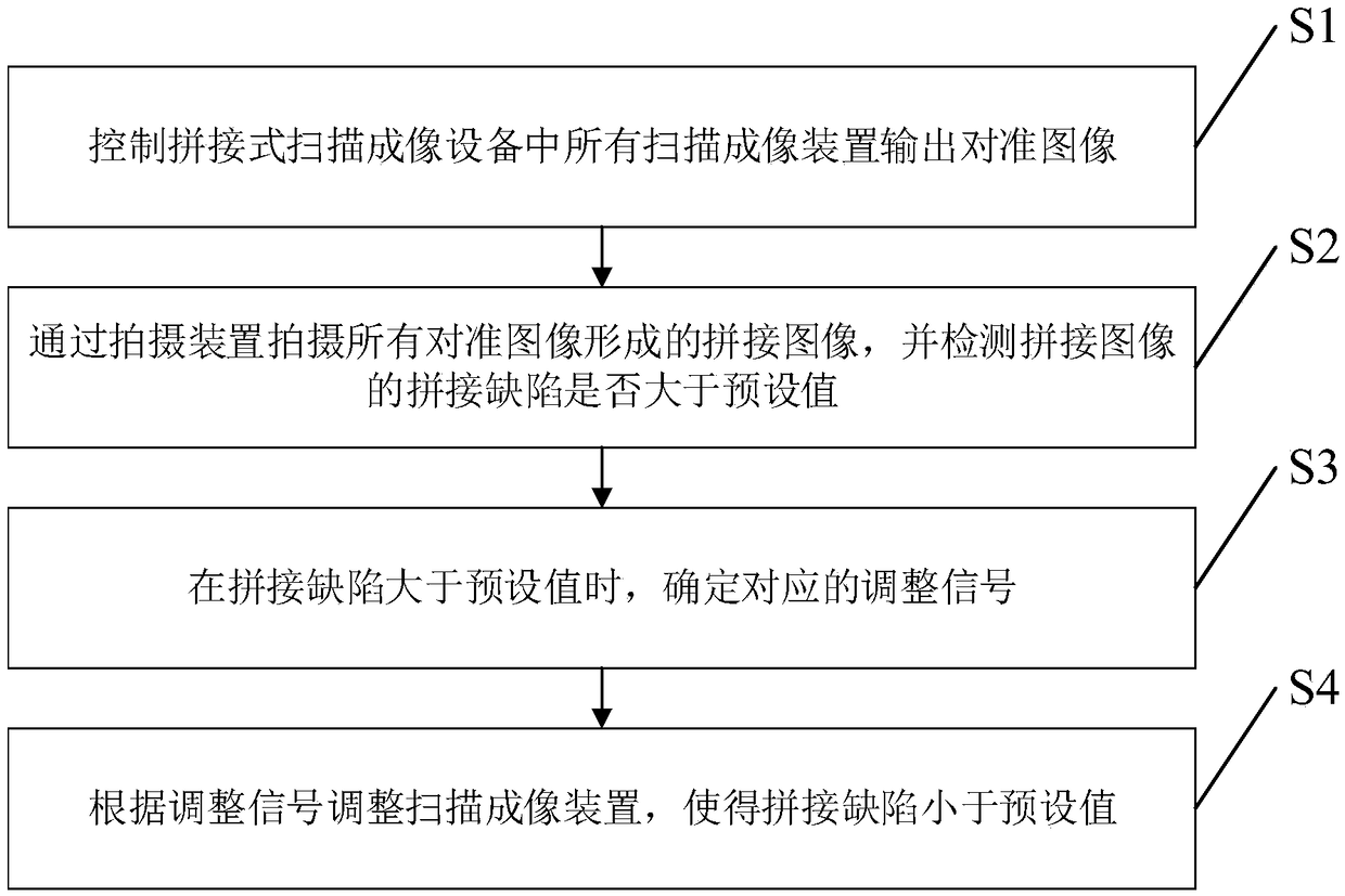
The invention discloses an adjustment method of splicing type scanning imaging equipment and the splicing type scanning imaging equipment. The adjustment method includes the following steps: controlling all scanning imaging devices in the splicing type scanning imaging equipment to output alignment images; shooting a splicing image formed by all the alignment images by using a shooting device, anddetecting whether a splicing defect of the splicing image is greater than a preset value; when the splicing defect is greater than the preset value, determining a corresponding adjustment signal; andadjusting the scanning imaging devices according to the adjustment signal to ensure that the splicing defect is less than the preset value. According to the technical scheme disclosed by the invention, in the case that the splicing defect of the splicing image formed by all the alignment images is less than the preset value, the splicing defect of the splicing image output by the splicing type scanning imaging equipment during normal operation is less than the preset value, that is, an image with a good splicing effect is output, and thus the time and effort that a user needs to spend can bereduced.

Description

technical field [0001] The invention relates to the field of laser scanning imaging, in particular to an adjustment method of splicing scanning imaging equipment and the splicing scanning imaging equipment. Background technique [0002] With the development of society, people have higher and higher requirements for display technology in fields such as the film and television animation industry and large conferences that require projectors, and the main requirements are reflected in high resolution and super large physical size. [0003] At present, in order to provide users with images of high resolution and large physical size, the images projected by multiple projectors are generally spliced ​​together. The distance between each projector and the projection screen will also change, and it is difficult to adjust to be consistent, so it will cause problems such as splicing gaps or image overlaps on the spliced ​​images on the projection screen. At this time, it is necessary ...

Claims


Application Information

Patent Timeline
IPC IPC(8): H04N9/31G06T3/40
CPCG06T3/4038G06T7/187G06T2207/10008H04N9/3188H04N9/3191
Inventor 宋海涛姚长呈
Owner CHENGDU IDEALSEE TECH
Learn More