


Quick Research
Generate reliable direction feasibility study reports for your R&D in just a few steps.

Technical Q&A
Discover and master advanced knowledge NOW. Basics, ideas, possibilities, all at once.

Find Solutions
As an expert in R&D theories, this can generate solutions to your technical problems instantly.

Evaluate Feasibility
Analyze your overall solution with one click, know your potential R&D risks in advance.

Monitor Landscape
Get weekly tech updates, stay abreast of the latest tech innovations and key insights.
Rotary working table
A technology of rotary workbench and workbench, which is applied in the direction of manufacturing tools, metal processing equipment, metal processing machinery parts, etc. It can solve the problems of workbench strength and precision influence, oil and gas pipeline winding, etc., so as to ensure repeat positioning accuracy and eliminate winding Effect
- Summary
- Abstract
- Description
- Claims
- Application Information
AI Technical Summary
Problems solved by technology
Method used
Image

Examples
Embodiment Construction
[0010] The rotary table will be further described in detail in conjunction with the accompanying drawings and specific implementation methods:
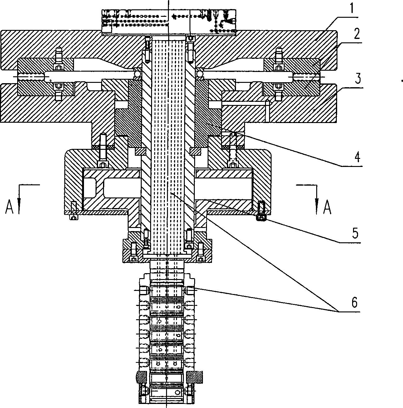
[0011] figure 1 As shown, the upper part of the end gear plate 2 is installed on the worktable 1, and the lower part is installed on the base. The center of the base 3 is located to form a sealed cavity, and the lifting and locking mechanism 4 is installed in the sealed cavity. Or pneumatic power to lift and lock the table, so that the rotary table can bear the force of heavy load on the side.
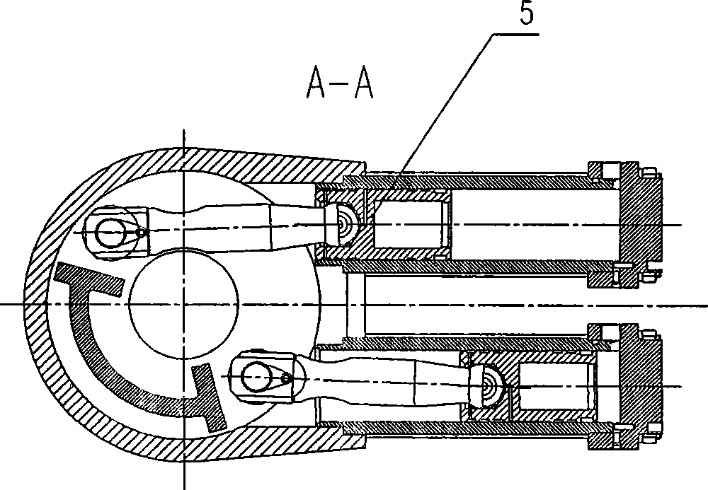
[0012] figure 2 yes figure 1 In the cross-sectional view of the lifting and locking mechanism 4, an intermediate rotating shaft 7 is installed, and the worktable 1 is fixed on the intermediate rotating shaft 7, and the 90-degree indexing drive mechanism 5 drives the intermediate rotating shaft 7 and the working table 2 to make intermittent rotations every 90 degrees. bit.
[0013] The intermediate rotating shaft 7 is a hollow shaft, which...
PUM
 Abstract
Description
Claims
Application Information
 - R&D Engineer
- R&D Manager
- IP Professional
- Industry Leading Data Capabilities
- Powerful AI technology
- Patent DNA Extraction
Browse by: Latest US Patents, China's latest patents, Technical Efficacy Thesaurus, Application Domain, Technology Topic, Popular Technical Reports.
© 2024 PatSnap. All rights reserved.Legal|Privacy policy|Modern Slavery Act Transparency Statement|Sitemap|About US| Contact US: help@patsnap.com