
Laser cutting method

A laser cutting and cutting direction technology, applied in laser welding equipment, metal processing equipment, welding equipment, etc., can solve problems such as carbonization and affecting cutting quality, and achieve the effects of reducing carbonization, improving cutting quality, and removing corner points

Active Publication Date: 2009-06-10
HANS CNC SCI & TECH
View PDF0 Cites 7 Cited by
  • Summary
  • Abstract
  • Description
  • Claims
  • Application Information

AI Technical Summary

Problems solved by technology

[0005] Figure 3 is a schematic diagram of the structure when cutting a rectangle. Each side shown in the figure will have an acceleration section and a deceleration section, and the junction between the side and the side (that is, the corner point) is severely carbonized. The reason is that the corner point is the starting point or end point of each side, and the closer to the corner, the slower the speed, so the laser near the corner is the most intensive, and carbonization will occur, seriously affecting the cutting quality

Method used


Image

  • Laser cutting method
  • Laser cutting method
  • Laser cutting method

Examples


Embodiment Construction

[0018] The present invention will be described in further detail below through specific embodiments and in conjunction with the accompanying drawings.

[0019] The laser cutting method of the present invention is mainly used for cutting non-metallic materials sensitive to lasers such as P / P boards. This is because non-metallic materials have high requirements on cutting quality, otherwise their quality will be affected. A new laser cutting method is designed for metal material cutting, which not only meets the cutting requirements, but also has high cutting quality.

[0020] Sometimes it is only necessary to cut the P / P board in a simple straight line, as shown in Figure 4, which is a schematic diagram of cutting a single straight line. When cutting, set the power and speed of laser cutting in advance, and then start the motor. The whole cutting steps are as follows:

[0021] Step 1: Place the motor on the left side of the desired cutting line, start the motor, and the motor d...


PUM


Abstract

The invention relates to a laser cutting method. Before cutting, a cutting head is accelerated to reach an end point to be cut, and does not emit laser at accelerating sections; after the cutting head reaches the end point to be cut, the laser begins emitting, and the cutting head cuts one side of a rectangle at a uniform speed; and after the cutting of the side is finished, a motor decelerates to drive the cutting head for running, and the laser does not emit at decelerating sections, thereby ensuring that the cutting of rectangular sides is finished under uniform speed state, completely removing angular points, simultaneously reducing carbonization, and improving the cutting quality.

Description

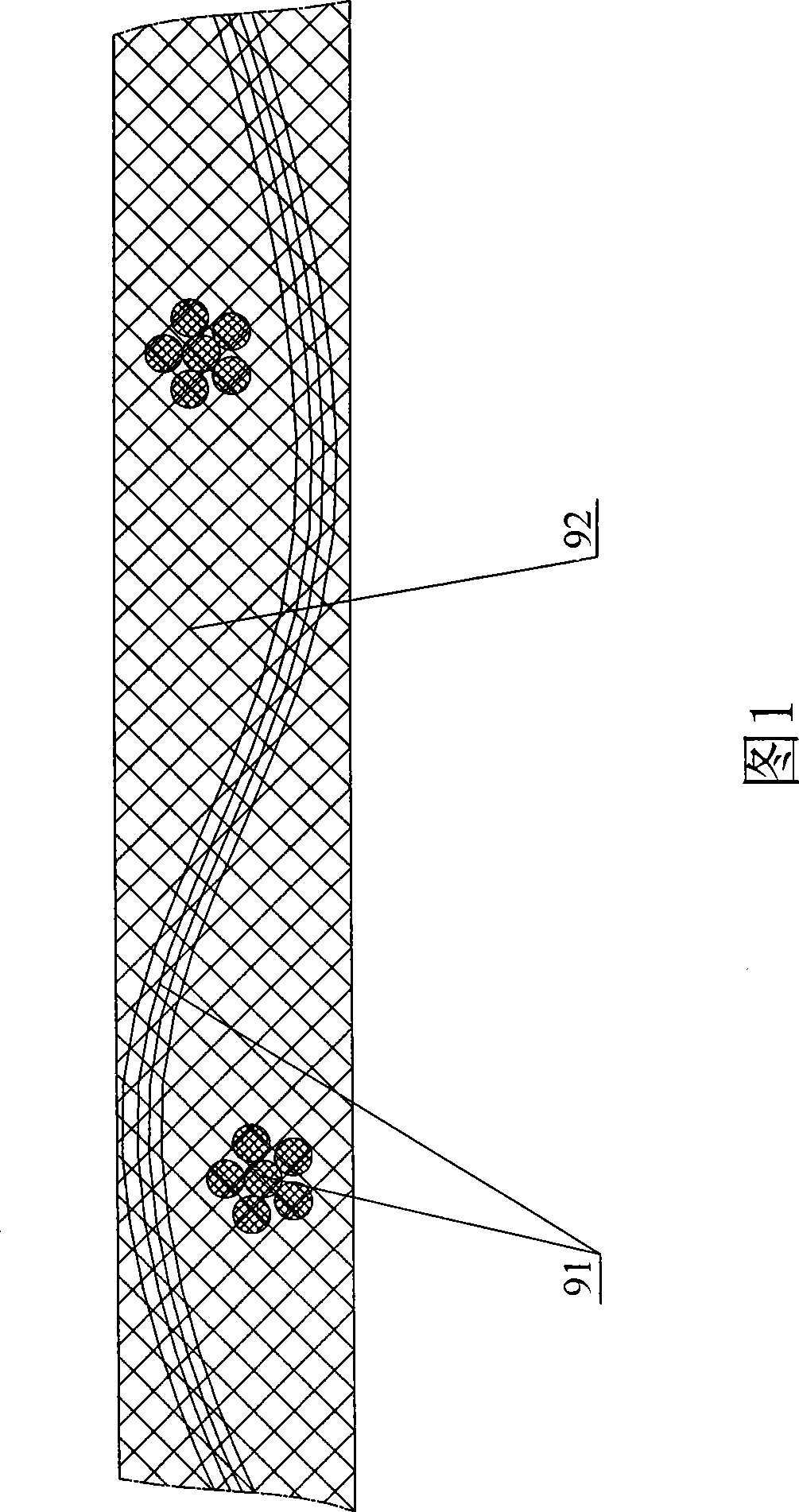
【Technical field】 [0001] The invention relates to the field of laser cutting, and is especially suitable for a high-speed cutting method of non-metallic materials sensitive to laser. 【Background technique】 [0002] The circuit board is composed of multi-layer copper foil wires and the insulating carrier between the copper foil wires. This carrier is the P / P board. In the process of manufacturing circuit boards, it is generally necessary to laser cut the P / P board. Please refer to Fig. 1, the P / P plate is made up of braided glass filament 91 and colloid 91 (epoxy resin) and is stored in a roll shape. The existing method of cutting P / P boards is to place the rolls of P / P boards on a proprietary device, and then laser cut the P / P boards into required sizes. [0003] However, since the P / P board is a laser-sensitive material, the current cutting method of this type of laser-sensitive material is that the carbonization of the beginning and end parts is relatively serious during ...

Claims


Application Information

Patent Timeline
Patent Type & Authority Applications(China)
IPC IPC(8): B23K26/40B23K26/38B23K26/08B23K26/042
Inventor 高云峰雷群翟学涛严超孙毅
Owner HANS CNC SCI & TECH
Learn More