Puncher

A piercing machine and open hole technology, which is applied in the field of piercing machines, can solve the problems of cost increase and achieve the effect of long life

Inactive Publication Date: 2009-06-10
UMIX
View PDF1 Cites 4 Cited by
  • Summary
  • Abstract
  • Description
  • Claims
  • Application Information

AI Technical Summary

Problems solved by technology

However, there is a problem that not only the cost increases but also management is required if the above two types of piercing machines are prepared.

Method used


Image

  • Puncher
  • Puncher
  • Puncher

Examples


Embodiment Construction

[0041] Next, examples will be described in detail as the best mode for carrying out the punching machine of the present invention.

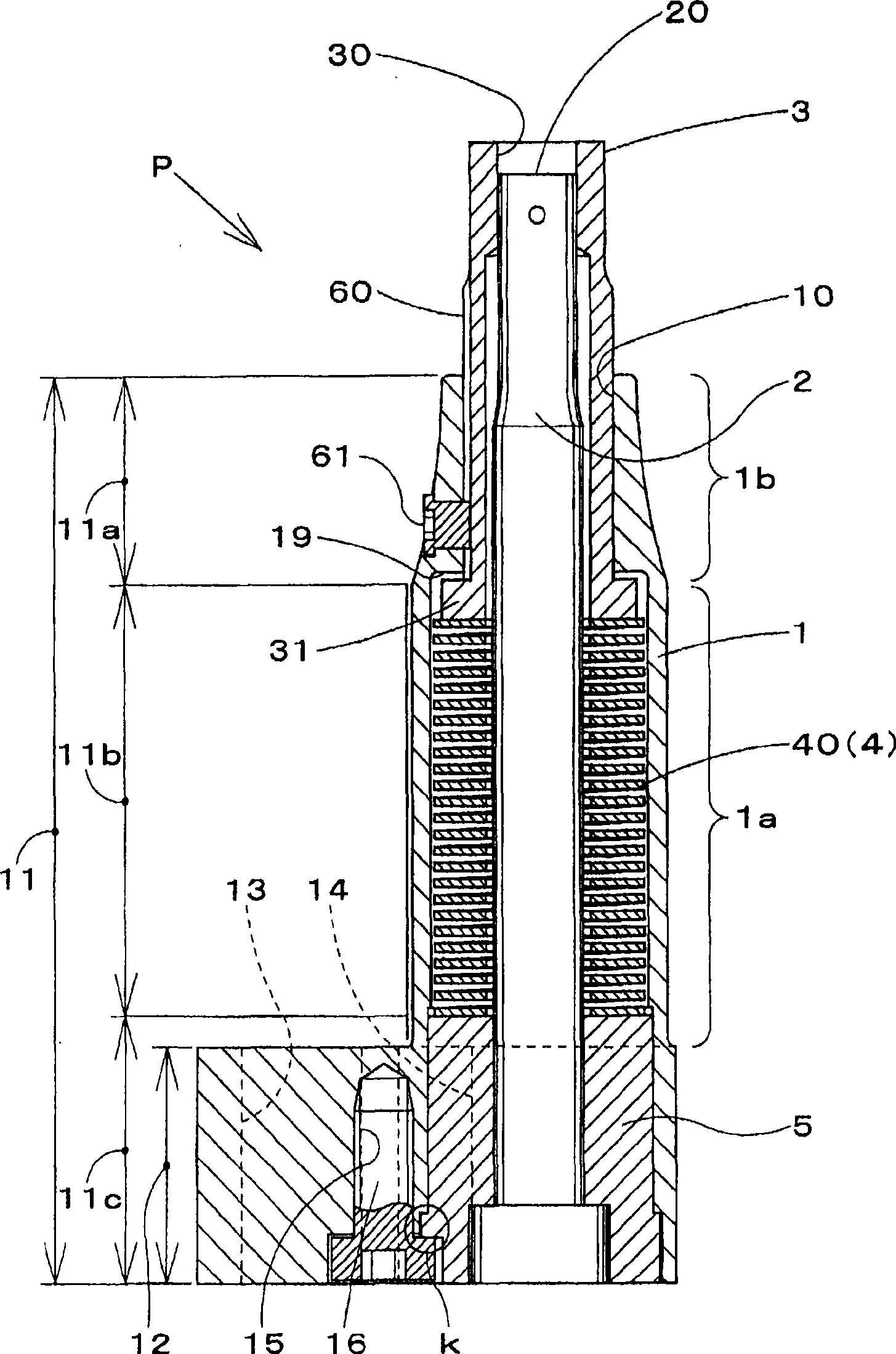
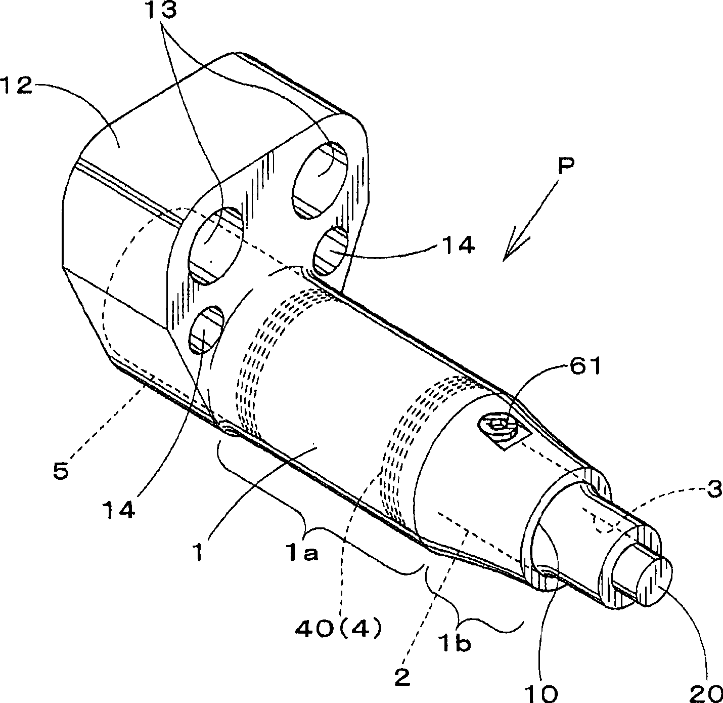
[0042] The piercing machine of the embodiment 1 of the application of the present invention is as Figure 1-6 shown. The piercer P as figure 1 or figure 2 As shown, in the state where the tip end surface 20 of the punch 2 has the one end open hole 10 protruding from the above-mentioned one end open hole 10 of the cylindrical cover, the punch 2 is held immovably by the punch. The device 5 is loosely inserted and arranged in the above-mentioned cover 1, and the cylindrical punching template 3 is set in a state of preventing the separation between the above-mentioned cover 1 and the punching punch 2, and the punching template is made by using the force applying device 4. 3 protrudes more from the open hole 10 than the piercing punch 2. And, utilizing the pressing force to the punching template 3 that overcomes the force of the above-mentioned ...


PUM


Abstract

The invention relates to a puncher; a piercing punch (2) is unmovably and loosely inserted in a cylindrical cover (1) having a one-end opening hole (10) while a tip end face (20) projects from the one-end opening hole (10). A cylindrical stripper (3) is provided between the cover (1) and the piercing punch (2) while the stripper (3) can be pulled out from the one-end opening hole (10). The stripper (3) is made to project more than the piercing punch (2) from the one-end opening hole (10) by an urging means (4). Then, pushing into the stripper (3) against the urging force of the urging means (4) makes the distal end face of the piercing punch (2) project from a through hole (30) bored at the projecting end of the stripper (3). A come-out prevention means for preventing the stripper from coming out from the cover is provided at the cover detachably.

Description

technical field [0001] The present invention relates to a punching machine for punching a workpiece with a punching punch while pressing a workpiece with a punching template. Background technique [0002] As a conventional punching machine 9 for punching, for example, in Japanese Patent Application / Japanese Laid-Open No. 2006-61938 (refer to image 3 ) is disclosed. [0003] Above-mentioned piercing machine 9 such as Figure 17 As shown, in the state where the top end surface of the punching punch 91 protrudes from the above-mentioned one-end opening hole 90a of the cylindrical cover 90 having the one-end opening hole 90a, the punching punch 91 cannot be held by the punch holder 94. Move and loosely insert in the cover 90, the cylindrical punching template 92 is set in the anti-off state between the above-mentioned cover 90 and the punching punch 91, and the compression coil spring 93 (urging device) is used to make this The punching template 92 protrudes from the open hol...

Claims


Application Information

Patent Timeline
Patent Type & Authority Applications(China)
IPC IPC(8): B21D28/24B21D28/34B21D28/26
CPCB21D45/08B21D28/34Y10T83/2159
Inventor 北村准敏
Owner UMIX
Why Eureka
Try Eureka