
Tandem resonant type fault current limit device

A fault current, series resonance technology, used in circuit devices, emergency protection circuit devices, emergency protection circuit devices for limiting overcurrent/overvoltage, etc.

Active Publication Date: 2011-03-23
CHINA ELECTRIC POWER RES INST +2
View PDF0 Cites 0 Cited by
  • Summary
  • Abstract
  • Description
  • Claims
  • Application Information

AI Technical Summary

Problems solved by technology

In the series resonant fault current limiter based on TPSC technology, the technology of using breakdown diode (BOD) to start and trigger the bypass of thyristor valve string has not been seen at home and abroad.

Method used


Image

  • Tandem resonant type fault current limit device
  • Tandem resonant type fault current limit device
  • Tandem resonant type fault current limit device

Examples


Embodiment Construction

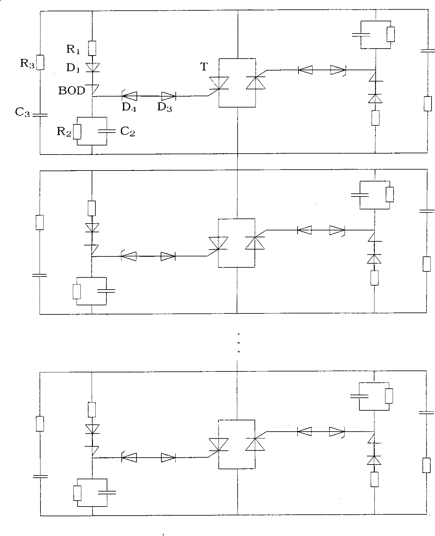
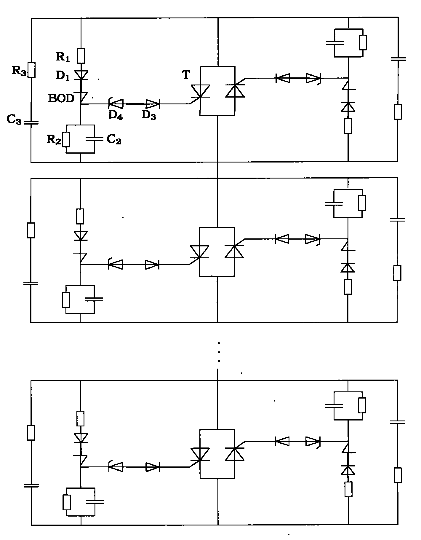
[0013] figure 1 It is a structural schematic diagram of a breakdown diode BOD start-triggering thyristor valve string bypass device for a series resonance fault current limiter based on a thyristor protection type series capacitor compensation TPSC technology of the present invention. The picture shows multiple thyristor valves in series (thyristor valve string), where BOD is a breakdown diode, T is a thyristor valve, and R 1 is the current limiting resistor, D 1 Fast recovery diodes in series, D 3 For the protection diode, D 4 is the zener diode, R 2 and C 2 It is a circuit to prevent false triggering of the thyristor, R 3 and C 3 It is the snubber circuit of the thyristor.

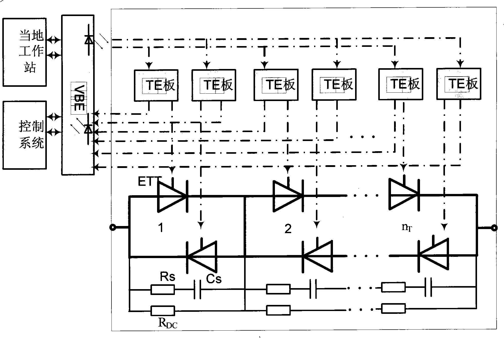
[0014] figure 2 It is a schematic diagram of thyristor valve trigger and detection signal flow. In the figure, VBE is the valve base electronics, TE board is the trigger and detection board, ETT is the thyristor, R s 、C s are the snubber resistor and snubber capacitor. R dc is the DC voltage...


PUM


Abstract

The invention provides a device for a breakdown diode to initiatively trigger a bypass of a thyristor valve string. The device comprises a plurality of thyristor valves connected in series and accessories thereof. A breakdown diode (BOD) is connected in a position between the gate pole and the positive pole of each thyristor valve. When faults such as short circuit happen in the electrical systemand a valve-based electronics (VBE) does not receive trigger signal of the thyristor valve string sent by a control and protection unit, the voltage at two ends of the thyristor valve string increases dramatically; when the forward voltage reaches the setting valve of breakdown voltage of the whole string of the breakdown diode (BOD), the breakdown diode (BOD) is converted to an on-state and sends trigger signal to the door poles of the thyristor valves depending on a sudden short circuit effect, the thyristor valves are in an on-state, and the valve-based electronics (VBE) automatically supplies trigger signals of the whole thyristor valve string according to a plurality of detected protection signals of the breakdown diode, so as to ensure that the thyristor valve string is in normal on-state for a period of time. The resistances and the capacitances connected in series arranged between the positive pole and the negative pole of each thyristor valve form a damp absorption circuit, and the resistances and the capacitances connected in parallel between the door pole and the negative pole of each thyristor valve form a circuit preventing the fault triggering of the thyristor. The limitation level of short circuit current is decided by the operation voltage of the breakdown diode. The damp absorption circuit restrains overvoltage in the closing process of the thyristor valves.

Description

technical field [0001] The invention relates to a thyristor valve string trigger and detection device in a power system and a power electronic device, in particular to a device for triggering a bypass of a thyristor valve string by a breakdown diode (BOD) in a fault current limiter. Background technique [0002] The existing breakdown diode (BOD) technology applied to power systems and power electronic devices, only a single breakdown diode triggers a single thyristor valve to prevent the forward overvoltage protection device of the thyristor valve, and the entire string of thyristors is not used. The action information of multiple breakdown diodes of the valve is used to detect faults such as short circuits in the power system and trigger the entire thyristor valve string. In the series resonant fault current limiter based on TPSC technology, the technology of using breakdown diode (BOD) to start and trigger thyristor valve string bypass has not been seen at home and abroad...

Claims


Application Information

Patent Timeline
Patent Type & Authority Patents(China)
IPC IPC(8): H02H9/02H02H9/08H03K17/72G01R19/165
Inventor 荆平戴朝波金雪芬武守远
Owner CHINA ELECTRIC POWER RES INST
Learn More