
Lining structure of electrical calcination furnace

A calcination furnace and lining technology, which is applied in the direction of electric furnace heating, furnace, overall lining, etc., can solve the problems of furnace lining material burnout, increase the temperature burden of steel furnace shell, reduce furnace wall heat dissipation, etc., and achieve product quality and production capacity guarantee, low operation and maintenance costs, and high utilization rate of electric and thermal energy

Active Publication Date: 2009-06-03
GUIYANG AL-MG DESIGN & RES INST
View PDF0 Cites 3 Cited by
  • Summary
  • Abstract
  • Description
  • Claims
  • Application Information

AI Technical Summary

Problems solved by technology

The defects of this lining structure are: 1) the temperature of the furnace wall is too high and the heat dissipation is large, which not only causes a large loss of electric energy, but also increases the temperature burden of the steel furnace shell, and also deteriorates the operating environment; 2) due to the There is no difference in the lining material along the axial direction. The lining temperature in the high-temperature zone in the middle of the furnace reaches the limit, while the low-temperature zone at the upper and lower ends of the furnace is far from the maximum service temperature of the lining, resulting in insufficient and reasonable utilization of the lining material.
[0003] Recently, some manufacturers simply thicken the lining of the furnace in an attempt to reduce the heat dissipation of the furnace wall, but then the lining material of the furnace is burned out due to the high temperature, resulting in a shutdown accident
Obviously, the existing lining structure of electric calciner is not ideal enough

Method used


Image

  • Lining structure of electrical calcination furnace

Examples


Embodiment Construction

[0017] Embodiments of the invention:

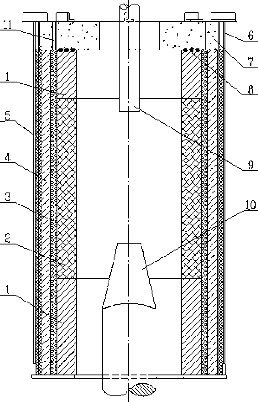
[0018] Outside the lining is a cylindrical furnace shell 6, and the upper part is a refractory castable furnace cover 7, which is sealed with an asbestos rope 8 between the furnace cover 7 and the refractory brick layer.

[0019] The refractory brick 1 is located on the innermost side of the furnace and is adjacent to the calcined material. One part is at the upper end of the furnace and the other is at the lower end of the furnace. The thickness of the brick layer is 160mm, and the inner diameter is φ1930mm. %, 0.2MPa load softening start temperature is 1520°C, and the normal temperature compressive strength is greater than 53.9MPa.

[0020] The central refractory brick 2 located in the highest temperature zone in the middle of the furnace is also located at the innermost side of the furnace and adjacent to the calcined material. The thickness of the brick layer is 160mm, and the inner diameter is φ1930mm. The material used is mullite br...


PUM

PropertyMeasurementUnit
thicknessaaaaaaaaaa
particle diameteraaaaaaaaaa
thicknessaaaaaaaaaa

Abstract

The invention discloses a lining structure of an electrical calcination furnace. The lining structure comprises a furnace shell (6) and a furnace cover (7); a refractory brick layer which is close to the center of the furnace is divided into two parts, that is, an end refractory brick part (1) positioned in low-temperature areas of the upper end and the lower end and a middle refractory brick part (2) positioned in a high-temperature area; a refractory insulating particle layer (3) is positioned outside the end refractory brick part (1) and the middle refractory brick part (2), an insulating layer (4) is positioned outside the refractory insulating particle layer (3), a ceramic fiber layer (5) is positioned outside the insulating layer (4), and the furnace shell (6) is positioned outside the ceramic fiber layer (5); and an upper electrode (9) is positioned in the center of the upper part of the furnace body, and a lower electrode (10) is positioned in the center of the lower part of the furnace body. The lining structure has the advantages of simple construction, wide temperature operating range, stable service performance, long service life, guaranteed quality and capacity of the product, high utilization rate of the electrical heat energy as well as low operation and maintenance cost.

Description

technical field [0001] The invention relates to a carbon calcination production equipment, in particular to an inner lining structure of an electric calcination furnace. Background technique [0002] At present, the production of electric calciner requires calcining the calcined coke to a high temperature above 1300°C, and the structure and material selection of the furnace lining are the most critical issues. In the prior art, a three-layer structure such as high alumina bricks, refractory brick particles and asbestos boards is used as the inner lining. The defects of this lining structure are: 1) the temperature of the furnace wall is too high and the heat dissipation is large, which not only causes a large loss of electric energy, but also increases the temperature burden of the steel furnace shell, and also deteriorates the operating environment; 2) due to the There is no difference in the lining material along the axial direction. The lining temperature in the high-tem...

Claims


Application Information

Patent Timeline
Patent Type & Authority Applications(China)
IPC IPC(8): F27D1/10F27D11/00F27D1/18F27D1/04
Inventor 陈宁
Owner GUIYANG AL-MG DESIGN & RES INST
Learn More