Drainage device for coal bed gas well electric submersible centrifugal pump

A technology for coalbed methane wells and centrifugal pumps, which is applied to pump devices, components of pumping devices for elastic fluids, pumps, etc., can solve problems such as high energy consumption, low pumping unit movement efficiency, and lack of energy conservation. The head and efficiency are stable, avoiding cavitation damage to the blades, and improving the output of a single well

Active Publication Date: 2009-06-03
北京超拓远大石油科技有限公司
View PDF6 Cites 18 Cited by
  • Summary
  • Abstract
  • Description
  • Claims
  • Application Information

AI Technical Summary

Problems solved by technology

2. High energy consumption: the movement efficiency of the pumping unit is low, and the energy consumption of driving equipment is relatively large, which does not save energy

Method used


Image

  • Drainage device for coal bed gas well electric submersible centrifugal pump
  • Drainage device for coal bed gas well electric submersible centrifugal pump

Examples


Embodiment 1

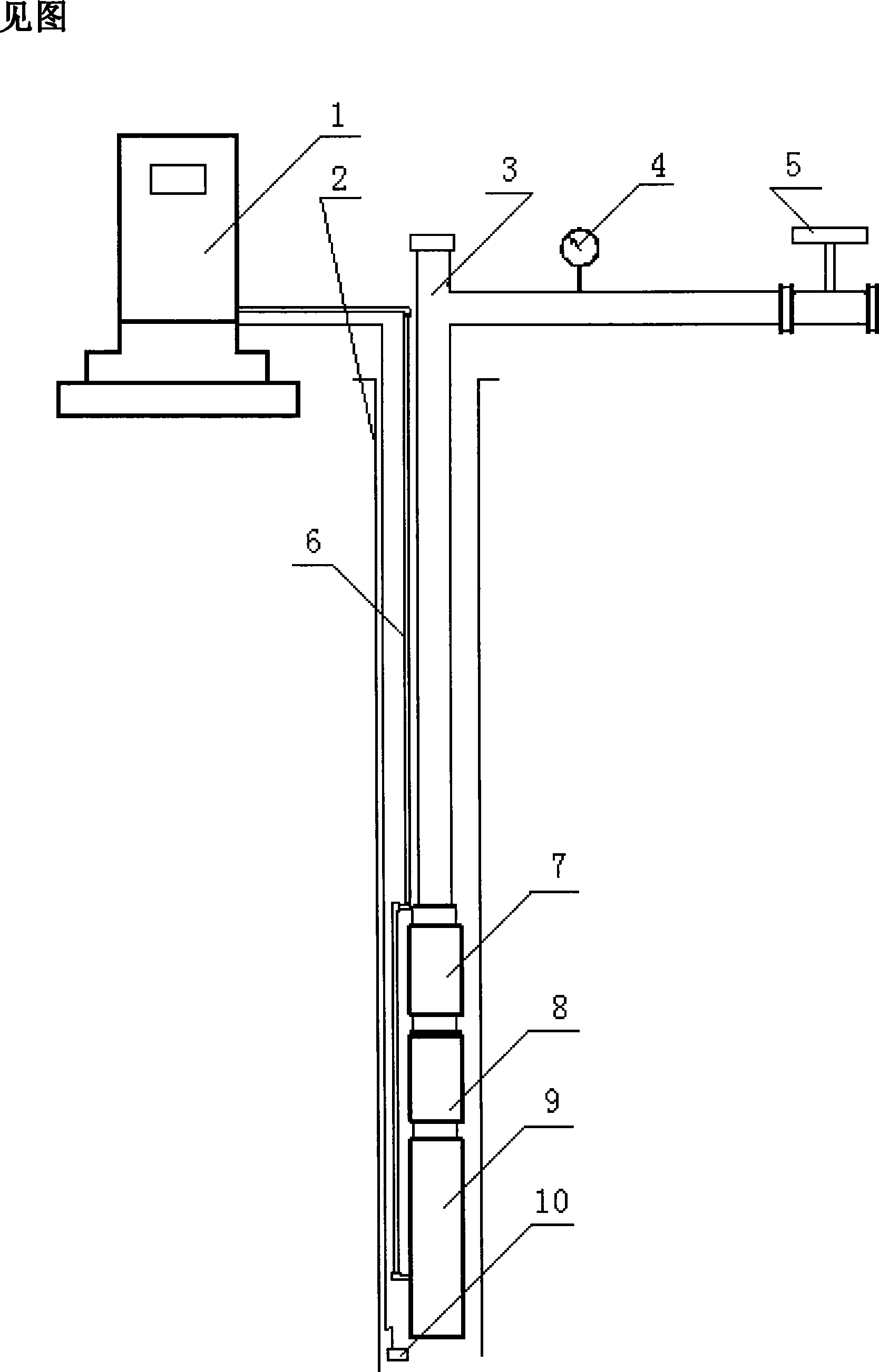
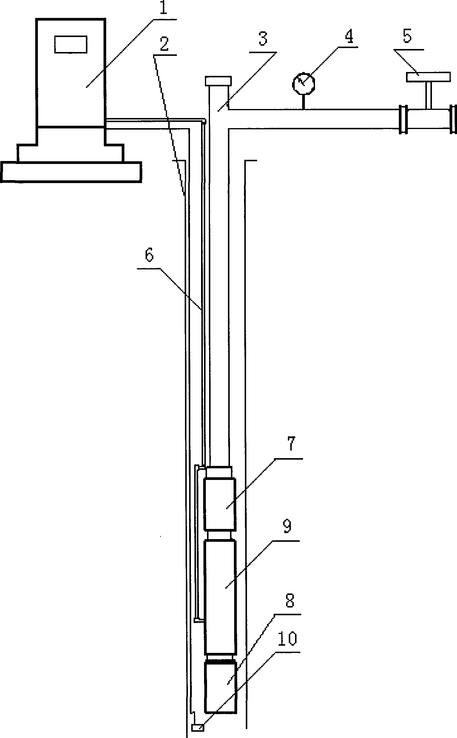
[0013] Embodiment 1: see figure 1 . The electric submersible centrifugal pump drainage device for coalbed gas wells of the present invention uses the electric submersible centrifugal pump 7 which is a large-lift multistage electric submersible centrifugal pump. The cable 6 connects the electric submersible centrifugal pump 7 and the controller 1 to provide power for the electric submersible centrifugal pump 7 . The electric submersible centrifugal pump 7 can reach 800 meters lift through the control system, 0.1m 3 / day traffic. The main components in the controller 1 include a central control unit (such as a PLC), a frequency converter, a man-machine interface, and the like. The controller 1 can realize the closed-loop control of the pump and the control of the flow regulator 5 of the water outlet. On the ground, the controller 1 has wires connected to the downhole drainage pump motor 9 . A horizontal liquid outlet pipeline is connected to the upper end of the oil pipe 3 ...

Embodiment 2

[0015] Embodiment 2: basically the same as Embodiment 1, the difference is:

[0016] The inlet end of the electric submersible centrifugal pump 7 is connected to the drainage pump motor 9 , and the lower end of the drainage pump motor 9 is connected to the gas-liquid separator 8 . There is a sleeve on the periphery of the drainage pump motor 9, and there is an annular channel between the inner wall of the sleeve and the casing of the drainage pump motor 9. The liquid separated by the gas-liquid separator 8 enters the inlet of the electric submersible centrifugal pump 7 after passing through the annular channel around the drainage pump motor 9 . When the liquid passes through the annular channel around the drainage pump motor 9, it can dissipate heat and cool down the drainage pump motor 9, protect the drainage pump motor 9 from stable operation, and prolong the service life.


PUM


Abstract

The invention provides a drainage device for a coal bed gas well electric submersible centrifugal pump, which is applied to the technical field of coal bed gas mining. The device is characterized in that a pressure sensor and a well head flow governor are fixed on an outlet line of liquid; the lower end of an oil pipe is connected with the outlet end of the electric submersible centrifugal pump; and the inlet end of the electric submersible centrifugal pump is connected with a motor of a drainage pump and a gas-liquid separator. The invention has the effects that (1) drainage function with large pump lift and low delivery capacity can be realized through intelligent control; (2) the gas-liquid separator can prevent soot from entering the electric submersible centrifugal pump, and can effectively realize that the coal bed gas is separated from water, thereby ensuring efficiency and stability of centrifugal pump operation; (3) an underground liquid level indicator can monitor height of an underground liquid surface in real time, thereby monitoring the effect of coal bed gas technology realization on one hand, and ensuring safe and stable operation at a high speed of the electric submersible centrifugal pump on the other hand; (4) under comprehensive effects of a controller, the flow governor, the underground liquid level indicator and the electric submersible centrifugal pump, technology of 'fixed-flow drainage' and 'fixed-liquid level drainage' needed in the process of coal bed gas exploitation can be realized.

Description

technical field [0001] The invention relates to the technical field of coalbed gas exploitation, in particular to a coalbed gas well drainage device, which is an electric submersible centrifugal pump drainage device for the coalbed gas well. Background technique [0002] my country is rich in coal resources, and coalbed methane contains CH 4 methane gas. In order to make full use of energy and solve the problem of energy shortage, the state strongly supports the exploitation of coalbed methane. [0003] At present, coalbed methane mining mainly adopts two methods: self-spraying mining and induced lifting mining. Induced lift mining is realized by pumping the confined water in the coal seam, reducing the pressure of the coal seam, and releasing the methane gas adsorbed in the coal seam. Usually, pumping unit piston pumps are used to realize the extraction of coalbed methane. There are some disadvantages in pumping unit type piston pump drainage, such as: 1. Intermittent w...

Claims


Application Information

Patent Timeline
Patent Type & Authority Applications(China)
IPC IPC(8): F04B47/06F04B53/00F04B53/08F04B49/00F04D13/08F04D15/00E21B43/00
Inventor 周宝星
Owner 北京超拓远大石油科技有限公司
Why Eureka
Try Eureka