Camera module

a camera module and camera technology, applied in the field of camera modules, can solve the problems of difficult control of the displacement of the camera module, and it is not possible for the camera module to exhibit its predetermined performance,

Inactive Publication Date: 2008-04-03
MITSUMI ELECTRIC CO LTD
View PDF2 Cites 10 Cited by
  • Summary
  • Abstract
  • Description
  • Claims
  • Application Information

AI Technical Summary

Benefits of technology

[0014]The present invention has been made in view of the problem described above, and therefore it is an object of the present invention to provide a camera module which can secure an accurate amount of displacement of a holder in response to a predetermined amount of an electrical current when the electrical current is supplied to a coil.

Problems solved by technology

However, there is a case that the biasing force of the deformed bridge portions 104c and 110c is larger or smaller than a predetermined biasing force due to poor assembly precision or variations in the spring characteristics of the bridge portions 104c and 110c.
If the holder 108 cannot be stably displaced in response to the predetermined amount of the electrical current supplied to the coil 107, it becomes difficult to control the displacement of the holder 108 accurately and therefore it is not possible for the camera module to exhibit its predetermined performance.

Method used


Image

  • Camera  module
  • Camera  module
  • Camera  module

Examples


Embodiment Construction

A camera module according to an embodiment of the present invention will be described below with reference to the accompanying drawing.

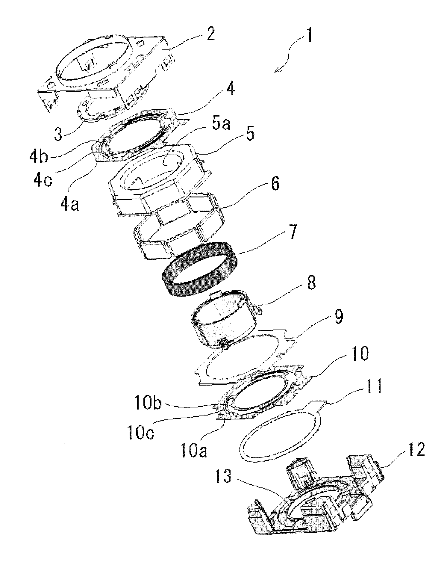
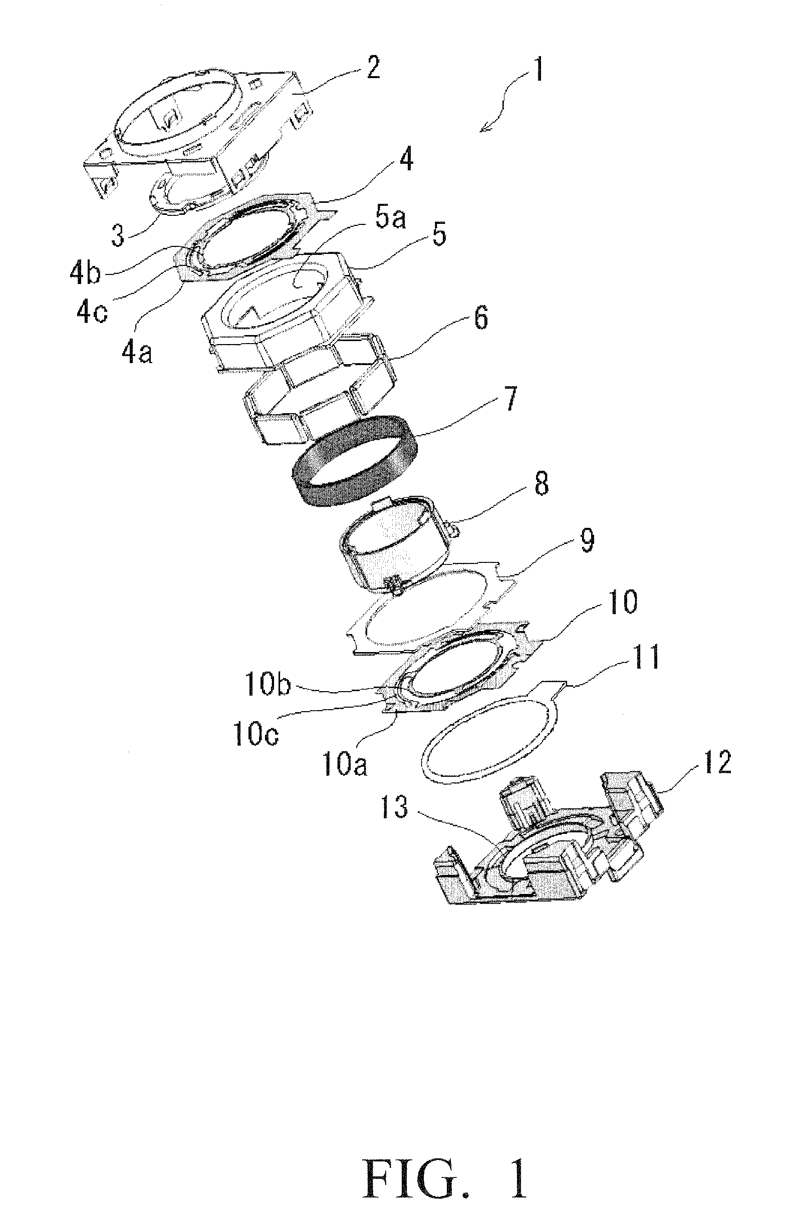
[0023]The camera module according to the embodiment comprises: a lens unit (not shown) which constitutes an optical system of the camera module; a holder 8 which houses the lens unit and is displaceable along an optical axis direction of the lens unit and has a cylindrical shape having upper and lower cylindrical end portions; a coil 7 provided on the holder 8; a yoke 5 and magnets 6 provided on the yoke 5 for providing a magnetic field to the coil 7; upper and lower leaf springs 4, 10 for supporting the holder 8 so that the holder 8 is displaceable along an optical axis direction of the lens unit; a base 12 for supporting the holder 8 when no electrical current is supplied to the coil 7; and an imaging element (not shown) provided below the lens unit. In this camera module, the upper and lower leaf springs 4, 10 bias the holder 8 toward the base 12 ...


PUM


Abstract

A camera module includes a lens unit which constitutes an optical system of the camera module; a holder which houses the lens unit and is displaceable along an optical axis direction of the lens unit; a coil provided on the holder; a yoke and magnets provided on the yoke for providing a magnetic field to the coil; a flexible printed circuit board to which the lead wires are connected for supplying an electrical current to the lead wires, the flexible printed circuit board having an insulating sheet portion and a pattern portion; a leaf spring for supporting the holder so that the holder is displaceable along an optical axis direction of the lens unit; a base for supporting the holder when no electrical current is supplied to the coil; and an imaging element provided below the lens unit. In the camera module the leaf spring biases the holder toward the base when no electrical current is supplied to the coil, the holder has a lower cylindrical end portion which is supported by the base, and the base has a support member which supports the lower cylindrical end portion of the holder and a protruding height adjusting mechanism which is capable of adjusting a protruding height thereof from the base.

Description

BACKGROUND OF THE INVENTION[0001]1. Field of the Invention[0002]This invention relates to a camera module, and more specifically to a camera module that can be used in small-sized electronic apparatuses such as digital cameras, camera-equipped cellular phones and the like.[0003]2. Description of the Related Art[0004]A camera module having a function of displacing a lens unit in a direction of an optical axis of the lens unit is used in relatively small-sized digital cameras, camera-equipped cellular phones and the like. This function is used for providing an autofocus function and / or zoom function and the like, and is achieved by an interaction between a magnetic field generated by an electrical current flowing in a coil and a magnetic field generated by a yoke and magnets provided on the yoke.[0005]Such a camera module includes a barrel which holds the lens unit, a holder which houses the barrel therein, and a pair of leaf springs for supporting the holder so that the holder is dis...

Claims


Application Information

Patent Timeline
Patent Type & Authority Applications(United States)
IPC IPC(8): G03B17/08
CPCG02B7/04H02K5/225H01F7/066G02B13/001
Inventor OSAKA, TOMOHIKOISHIZAWA, TAKASHI
Owner MITSUMI ELECTRIC CO LTD
Why Eureka
Try Eureka