Image device
A technology of a camera device and a camera unit, which is applied in the field of hand shake correction technology and can solve the problems of conspicuous noise components and the like
- Summary
- Abstract
- Description
- Claims
- Application Information
AI Technical Summary
Problems solved by technology
Method used
Image
Examples
Embodiment approach 1
[0064] (Embodiment 1: Outline) This embodiment relates to an imaging device for determining whether to perform hand-shake correction synthesis in accordance with illuminance conditions, and to perform hand-shake correction synthesis using a plurality of images captured under different imaging conditions Synthesize images without hand shake.
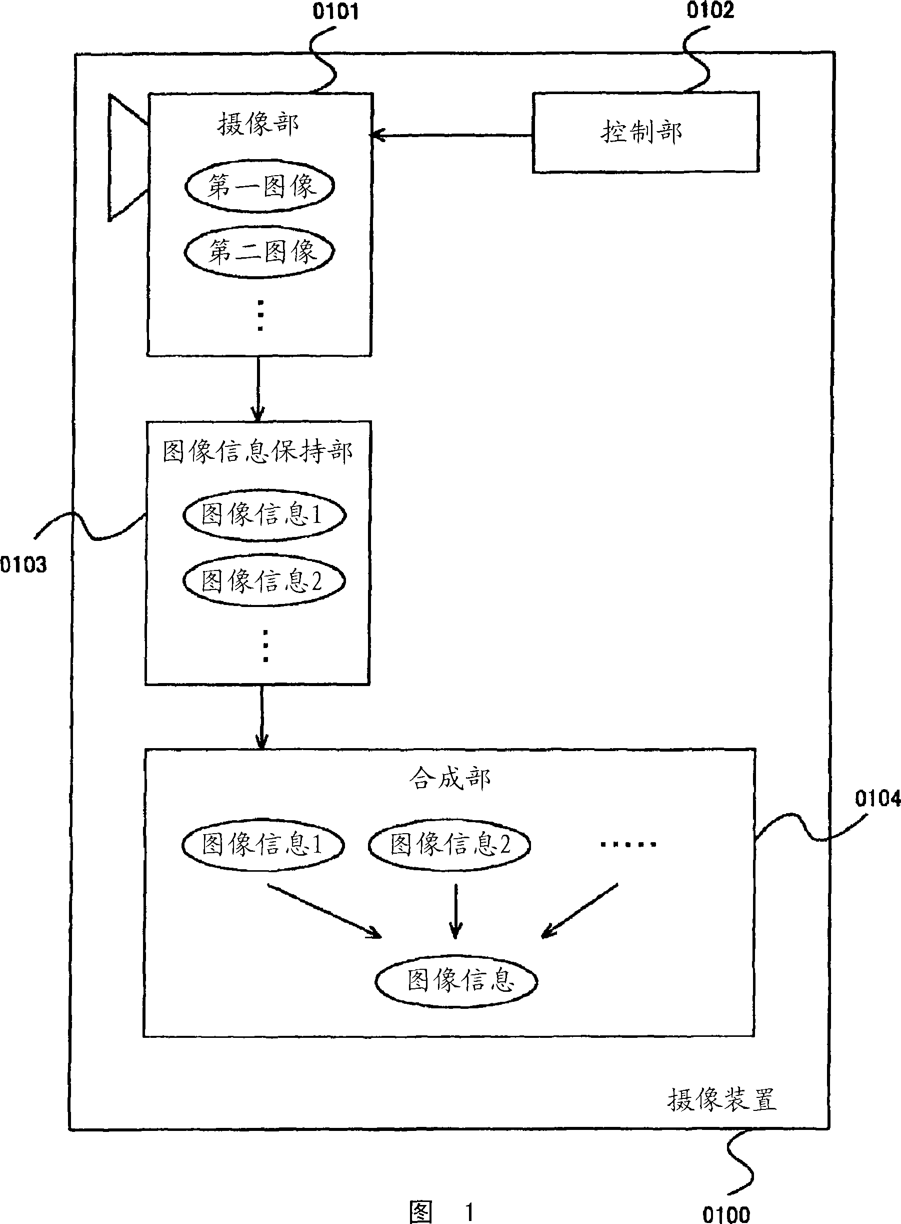
[0065] (Embodiment 1: Configuration) Functional blocks of an imaging device according to this embodiment are illustrated in FIGS. 1 and 2 . The imaging device (0100) illustrated in FIG. 1 includes an "imaging unit" (0101), a "control unit" (0102), an "image information storage unit" (0103), and a "synthesis unit" (0104).
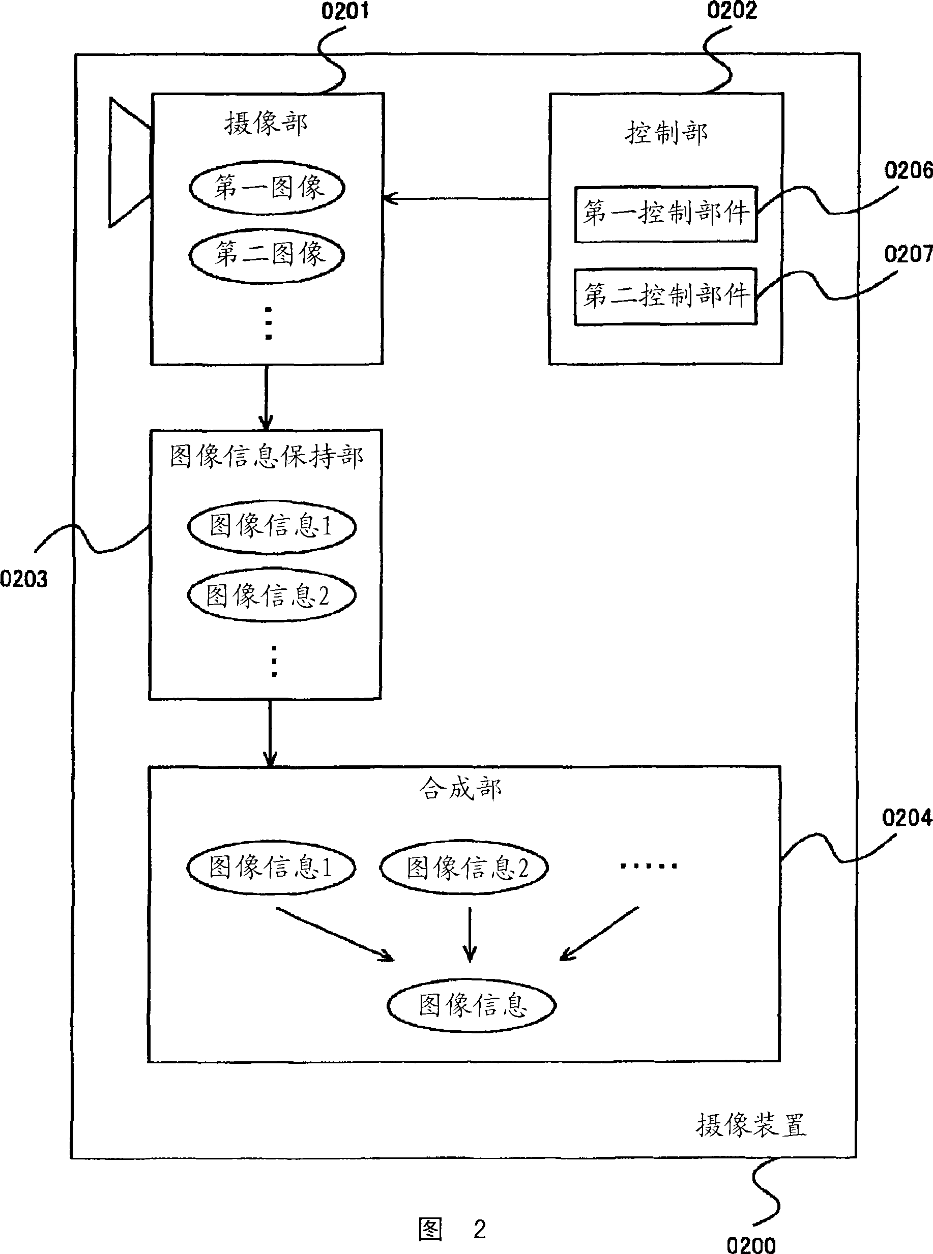
[0066] In addition, as shown in FIG. 2, the imaging device (0200) has an "imaging unit" (0201), a "control unit" (0202), an "image information storage unit" (0203), and a "synthesis unit" (0204), Furthermore, the control unit (0202) may have "first control means" (0206) and "second control means" (0207).
[0067] In a...
Embodiment approach 2
[0106] (Embodiment 2: Outline) The present embodiment relates to an imaging device that synthesizes an image without hand shake using a plurality of images captured under different imaging conditions. It is possible to obtain a hand-shake corrected image in which noise is suppressed without a large change in image quality under a slight change in illuminance environment.
[0107] (Embodiment 2: Configuration) FIG. 8 illustrates functional blocks of an imaging device according to this embodiment. The configuration of the imaging device according to this embodiment is a configuration in which "first combining ratio variable combining means" (0808) is added to the configuration of the imaging device shown in FIGS. 1 and 2 described in the first embodiment. FIG. 8 exemplifies a configuration in which the first combining ratio variable combining means (0808) is added to the configuration of the imaging device explained in FIG. 2 . The imaging device (0800) includes an "imaging uni...
Embodiment approach 3
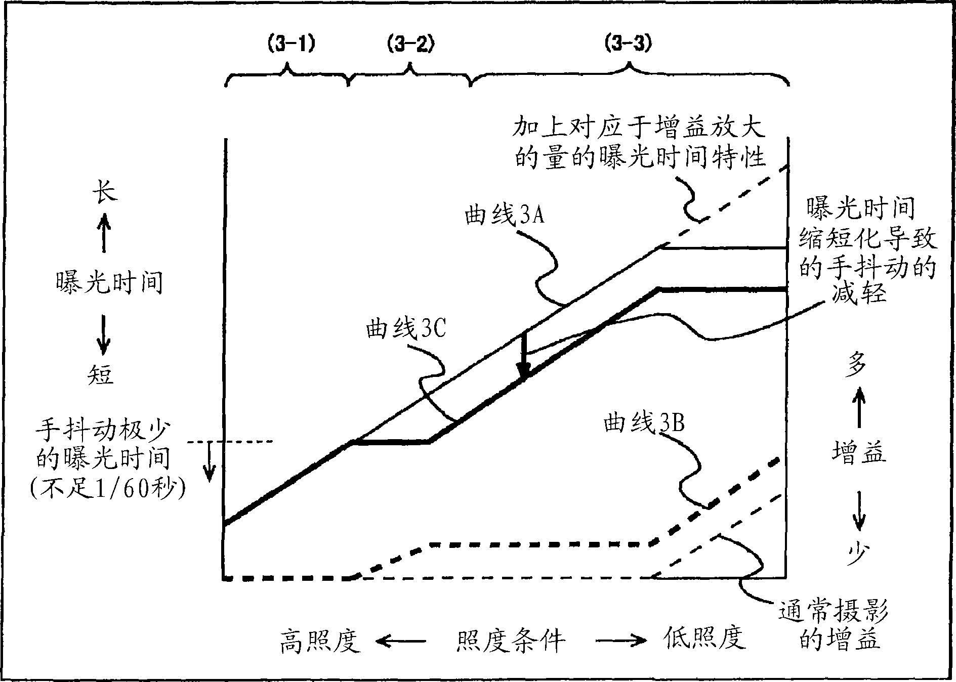
[0126] (Embodiment 3: Outline) This embodiment relates to an imaging device in which gain amplification is applied in order to compensate underexposure of the second image due to shortened exposure time in a somewhat dark low-light environment. In the case of compositing, in the dark part where the light does not reach the subject sufficiently, it is possible to perform compositing that uses an image with less noise to further increase the weight, so that the dark part where the light does not reach the subject sufficiently is suppressed. image with good quality without noise.
[0127] (Embodiment 3: Configuration) The functional blocks of the imaging device of this embodiment are illustrated in FIG. 10 . The configuration of the imaging device of this embodiment is a configuration in which "brightness information acquisition means" (1008) and "second synthesis ratio variable synthesis means" (1009) are added to the configuration of the imaging device described in Embodiment 1...
PUM
 Abstract
Description
Claims
Application Information
 - R&D Engineer
- R&D Manager
- IP Professional
- Industry Leading Data Capabilities
- Powerful AI technology
- Patent DNA Extraction
Browse by: Latest US Patents, China's latest patents, Technical Efficacy Thesaurus, Application Domain, Technology Topic, Popular Technical Reports.
© 2024 PatSnap. All rights reserved.Legal|Privacy policy|Modern Slavery Act Transparency Statement|Sitemap|About US| Contact US: help@patsnap.com


