Method, apparatus, system for clipping signal and signal radiation system
A clipping and signal technology, applied in the fields of signal transmission system, signal clipping, and signal processing, can solve the problem of occupying large hardware resources, and achieve the effect of reducing pressure and simple logic design.
- Summary
- Abstract
- Description
- Claims
- Application Information
AI Technical Summary
Problems solved by technology
Method used
Image


Examples
Embodiment 1
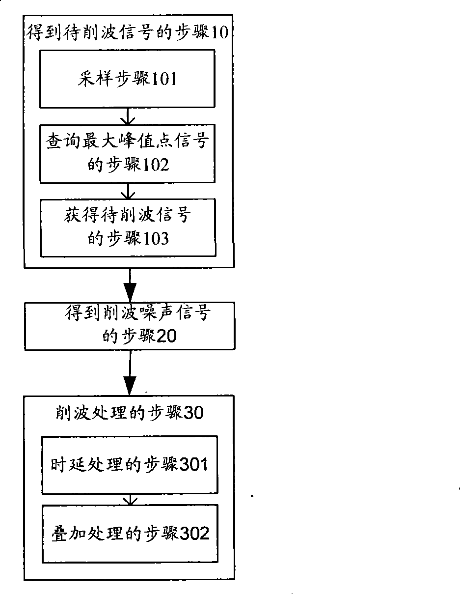
[0030] like figure 1 The flowchart of the signal clipping method shown in the present embodiment proposes a signal clipping method, including:
[0031] Step 10 of obtaining the signal to be clipped: sampling the input signal and detecting the maximum peak point signal exceeding the preset threshold, and using the sampling point signal centered on the maximum peak point signal as the signal to be clipped, it can be known that, The peak point signal can be regarded as a noise signal exceeding the preset threshold, here a maximum peak point signal is found according to the preset threshold;
[0032] Step 20 of obtaining a clipping noise signal: multiplying the maximum peak point signal by a preset clipping coefficient to obtain a clipping noise signal;
[0033] Step 30 of clipping processing: reversely superimposing the clipping noise signal on the signal to be clipped to complete clipping processing.
[0034] In the above signal clipping method, the input signal may be a combi...
Embodiment 2
[0037] This embodiment proposes a signal clipping method, including: Step 10 of obtaining the signal to be clipped: sampling the input signal and detecting the maximum peak point signal exceeding the preset threshold, and centering on the maximum peak point signal The sampling point signal is used as the signal to be clipped; the step 20 of obtaining the clipping noise signal: multiplying the maximum peak point signal with the preset clipping coefficient to obtain the clipping noise signal; the step 30 of clipping processing: The clipping noise signal is reversely superimposed on the signal to be clipped to complete the clipping process.
[0038] Specifically, as figure 2 Shown, at first, include in the step 10 that obtains signal to be clipped:
[0039] Sampling step 101: see image 3 The principle diagram of the clipping queue is explained by the signal flow direction. The initial sampling point signal 1 is input into the clipping queue in sequence according to a certain ...
Embodiment 3
[0052] like Figure 4 As shown, this embodiment proposes a signal clipping method, which can perform k-level clipping processing on an input signal. The choice of k series is mainly based on the peak-to-average ratio of the signal. Some signals only need one level to complete the control of the peak-to-average ratio, but the peak-to-average ratio signal must be multi-level to achieve, k>1. After the multi-carrier signal is digitally up-converted / combined, the output signal is further transmitted to the power amplifier through digital pre-distortion after k-level clipping processing.
[0053] Specifically, see image 3 The principle schematic diagram of the clipping queue illustrates k-level clipping processing. After m clipping processing is performed on the sampling point signals corresponding to the 2n sampling point data of the middle two frames n: 2n-1——3n-1, the first frame of the queue is 3n : The sampling point signal 9 corresponding to the n sampling point data of 4n...
PUM
 Abstract
Description
Claims
Application Information
 - Generate Ideas
- Intellectual Property
- Life Sciences
- Materials
- Tech Scout
- Unparalleled Data Quality
- Higher Quality Content
- 60% Fewer Hallucinations
Browse by: Latest US Patents, China's latest patents, Technical Efficacy Thesaurus, Application Domain, Technology Topic, Popular Technical Reports.
© 2025 PatSnap. All rights reserved.Legal|Privacy policy|Modern Slavery Act Transparency Statement|Sitemap|About US| Contact US: help@patsnap.com