
Card connector

一种卡连接器、接触焊盘的技术,应用在容纳小型卡的连接器领域,能够解决卡外壁损坏等问题,达到可靠阻止的效果

Active Publication Date: 2009-05-13
MOLEX INC
View PDF1 Cites 1 Cited by
  • Summary
  • Abstract
  • Description
  • Claims
  • Application Information

AI Technical Summary

Problems solved by technology

Also in the incorrectly inserted card, a part of the card is subjected to a reaction force from the engagement protrusion 307, and like this, the part forming the outer wall of the card may be damaged.

Method used


Image

  • Card connector
  • Card connector
  • Card connector

Examples


Embodiment Construction

[0031] Preferred embodiments of the present invention will be described in detail below with reference to the accompanying drawings.

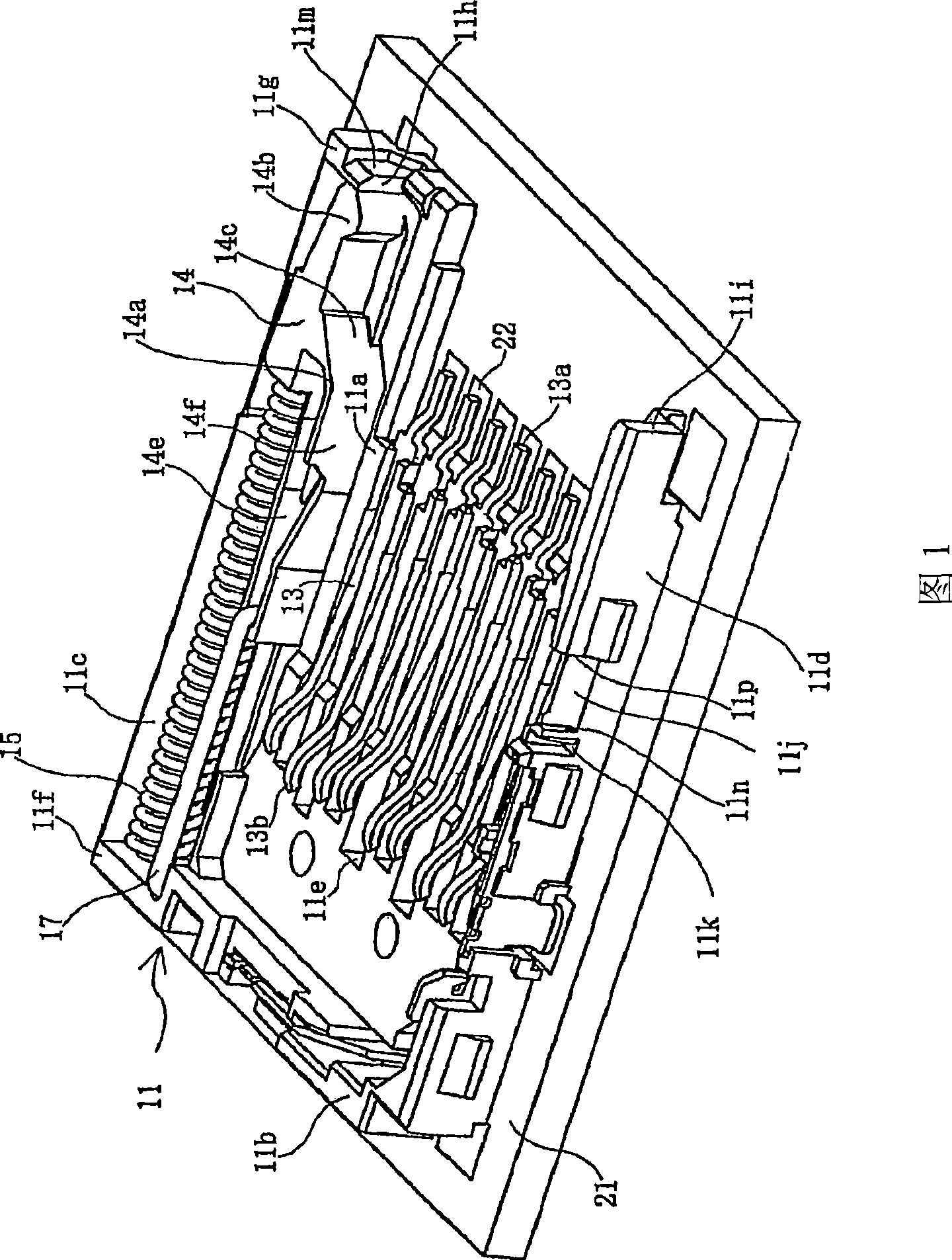
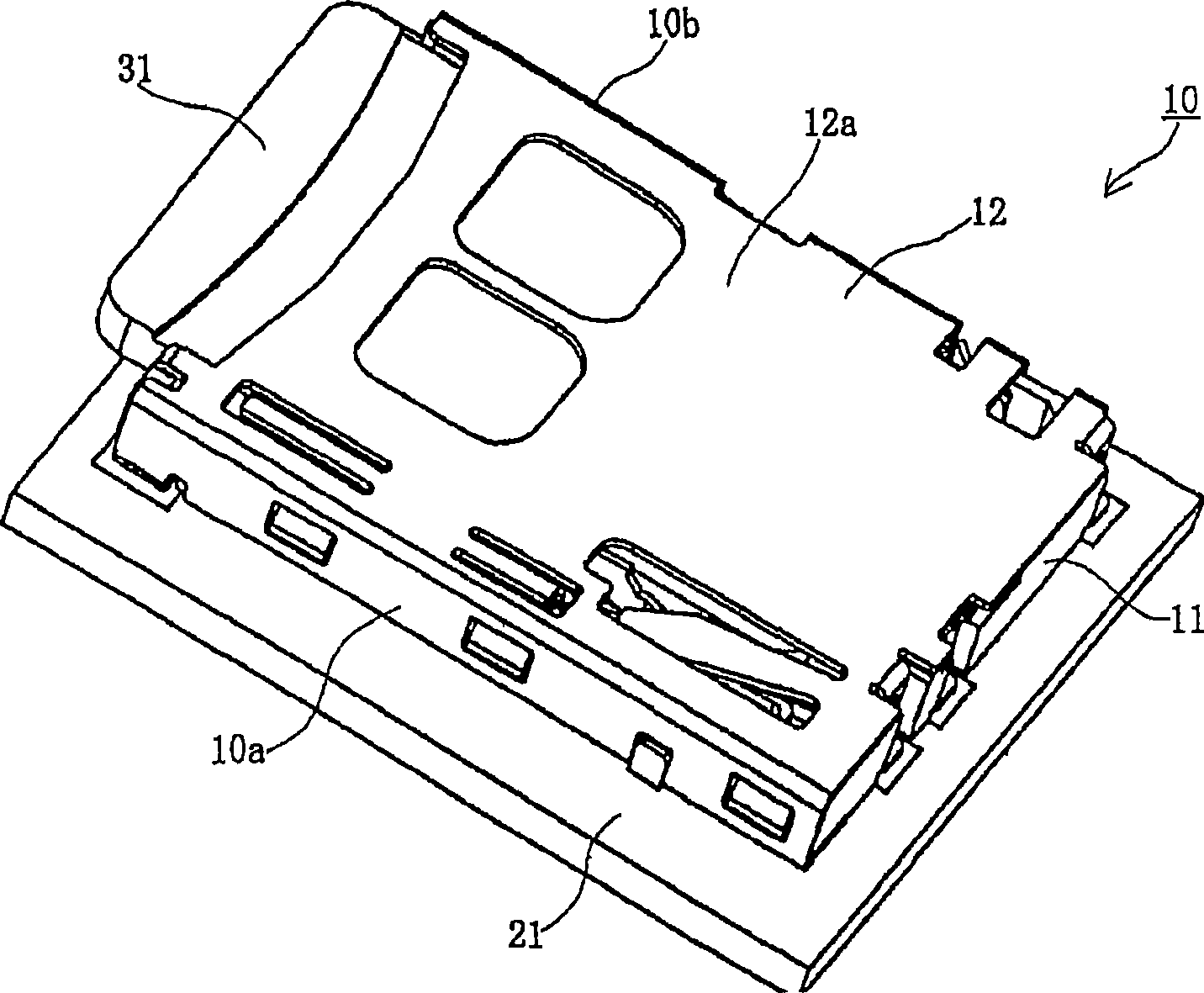
[0032] 1-4, the preferred embodiment card connector 10 is mounted on a substrate 21, such as a printed circuit board provided in an electronic device (not shown). The card 31 is inserted into the card connector 10 so that the card 31 is mounted in the electronic device through the card connector 10 . For example, the electronic device may be any type of device, such as a personal computer, a portable or mobile phone, a PDA, a digital camera, a video camera, a music player, a game console, and a car navigation system, among others.

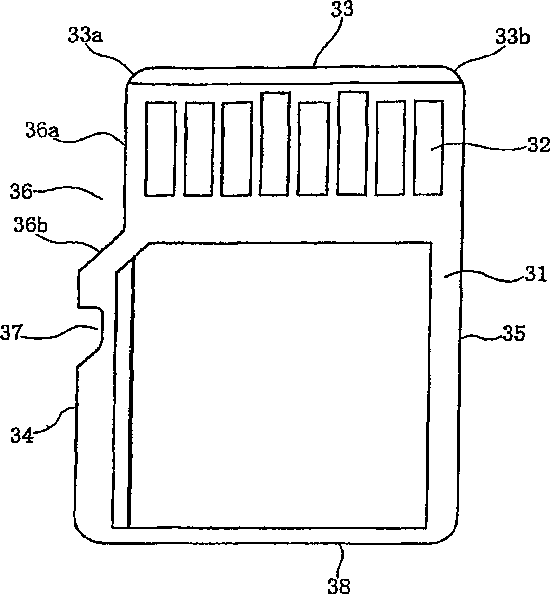
[0033] The card 31 is substantially in the shape of a rectangular plate. In the area near the front end portion 33 of one surface of the card 31, a plurality of exposed contact pads 32 functioning as terminal parts are arranged, such as image 3 shown. No contact pads 32 are arranged on the other surface of the c...


PUM


Abstract

A card connector is configured for receiving a generally rectangular card therein. The card has contact pads and generally parallel first and second sides with a cut-away portion formed in the first side in proximity to a front end of the card. The cut-away portion includes a short length extending from the front end generally parallel to the first side, and a tapered shoulder part extending from the short length to the first side. The connector includes an insulative housing with first and second spaced apart sidewalls that define a cavity therein for receiving the card in an insertion direction. A tapered surface is provided adjacent the first sidewall to guide an improperly inserted card at an angle to the insertion direction and a second sidewall recess is formed in the second sidewall to permit entrance of a corner part of such improperly inserted card. A plurality of electrically conductive terminals are mounted in the housing and configured to engage the contact pads of the card upon proper insertion of the card into the housing. A metal shell is also mounted on the housing.

Description

technical field [0001] The present invention relates to a card connector, and more particularly to a connector for accommodating miniature cards. Background technique [0002] Generally speaking, electronic devices such as personal computers, mobile or mobile phones, PDAs (Personal Digital Assistants), digital cameras, video cameras, music players, game consoles, and car navigation systems are equipped with card memory card, e.g. mini SD Card, TransFlash Card, Micro SD card etc. [0003] Recently, the rapid miniaturization of electronic equipment has created a trend of rapid miniaturization of memory cards and card connectors. The card connector tends to be arranged at almost invisible locations, such as the sides and bottom edges of electronic equipment, while excluding locations where components such as display screens, operation buttons, etc. are arranged. Accordingly, the card may be inserted upside down, ie incorrectly. If the card is inserted incorrectly, the ...

Claims


Application Information

Patent Timeline
Patent Type & Authority Applications(China)
IPC IPC(8): G06K7/00G06K13/08
CPCG06K13/08G06K7/0021G06K19/07H01R12/71
Inventor 松本保吉宫泽顺一冨田光洋高瀬尚人开田绫子
Owner MOLEX INC
Learn More