
Method and apparatus for hydraulic jet side drilling for radial branching borehole

A technology of hydraulic jetting and branch wells, which is applied in liquid/gas jet drilling, drilling equipment and methods, drilling equipment, etc., and can solve the problems of low efficiency of window opening tools, high cement strength requirements, and slow rock breaking speed of drill bits, etc. , to achieve the effect of high-efficiency increase in production recovery, reduce labor intensity, and avoid downhole accidents

Active Publication Date: 2013-07-10
CHINA UNIV OF PETROLEUM (BEIJING)
View PDF0 Cites 0 Cited by
  • Summary
  • Abstract
  • Description
  • Claims
  • Application Information

AI Technical Summary

Problems solved by technology

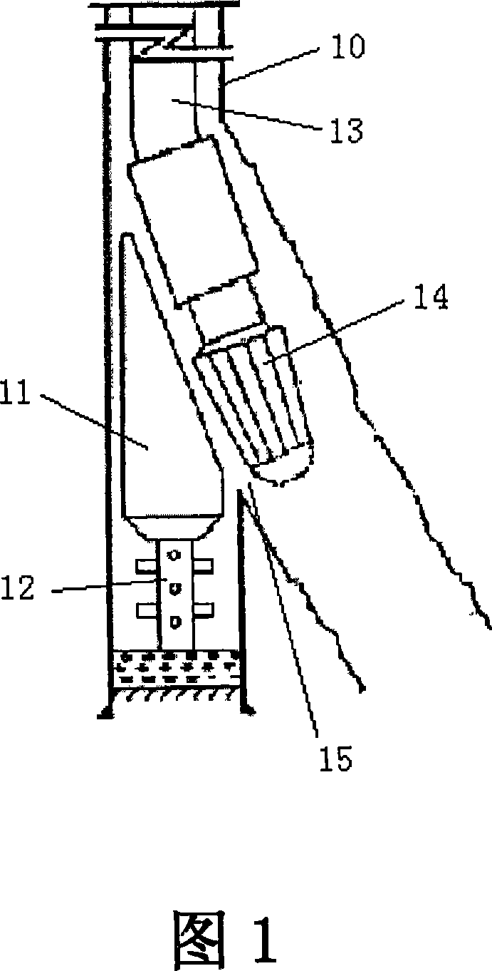
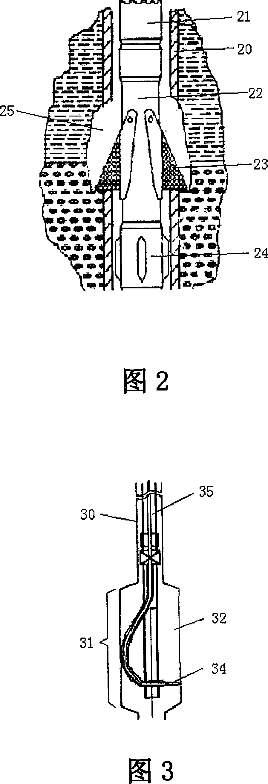
The main problems of the window milling method in this section are: the efficiency of the window opening tool is low; the rock breaking speed of the drill bit is slow; the amount of milling iron chips is large and the shape is large, and it is difficult to remove; after the section milling, the window opening must be sealed with cement. That is, it is often said in the field that large cement plugs are waiting for setting, and the strength of cement is required to be high.
The main problems of this technology are: the preparatory work is relatively complicated, the pipe string needs to be lowered several times for section milling and reaming, the drilling cycle is long, and the operation procedure is relatively complicated

Method used


Image

  • Method and apparatus for hydraulic jet side drilling for radial branching borehole
  • Method and apparatus for hydraulic jet side drilling for radial branching borehole
  • Method and apparatus for hydraulic jet side drilling for radial branching borehole

Examples


Embodiment approach 1

[0052] Please refer to FIG. 4A , which is a flow chart of the first technical solution of the hydrojet sidetracking radially branched wellbore method of the present invention. The method for sidetracking the radially branched wellbore of the scheme in the present invention comprises the following steps:

[0053] (1) Put the first oil pipe 40 with the diverter 44 fixed at the end into the oil well casing 50, and drop it to a specified depth; wherein, the outer dimension of the diverter 44 is smaller than the inner diameter of the casing 50, by The through passage provided in the diverter 44 connects the top and the side wall of the diverter; please refer to FIG. 5 for cooperation;

[0054] (2) Fix the first oil pipe 40 and the casing 50 by the oil pipe anchor 41 arranged on the first oil pipe 40, so that the diverter 44 is fixed at the specified depth position;

[0055] (3) Put the second oil pipe (not shown in the figure) whose outer diameter is smaller than the inner diamete...

Embodiment approach 2

[0068]Please refer to FIG. 4B , which is a flow chart of the second technical solution of the hydrojet sidetracking radially branched wellbore method of the present invention. The method for sidetracking the radially branched wellbore of the scheme in the present invention comprises the following steps:

[0069] (1) Put the first oil pipe 40 with the diverter 44 fixed at the end into the oil well casing 50, and drop it to a specified depth; wherein, the outer dimension of the diverter 44 is smaller than the inner diameter of the casing 50, by The through passage arranged in the diverter 44 communicates with the top and the side wall of the diverter;

[0070] (2) Fix the first oil pipe 40 and the casing 50 by the oil pipe anchor 41 arranged on the first oil pipe 40, so that the diverter 44 is fixed at the specified depth position;

[0071] (3) Put the second oil pipe whose outer diameter is smaller than the inner diameter of the first oil pipe 40 into the first oil pipe, and a...

Embodiment approach 3

[0082] Please refer to FIG. 4C , which is a flow chart of the third technical solution of the hydrojet sidetracking radially branched wellbore method of the present invention. The method for sidetracking the radially branched wellbore of the scheme in the present invention comprises the following steps:

[0083] (1) Put the first oil pipe 40 with the diverter 44 fixed at the end into the oil well casing 50, and drop it to a specified depth; wherein, the outer dimension of the diverter is less than or equal to the inner diameter of the casing, by setting The through channel in the diverter 44 communicates with the top and side walls of the diverter;

[0084] (2) Fix the first oil pipe 40 and the casing 50 by the oil pipe anchor 41 arranged on the first oil pipe 40, so that the diverter 44 is fixed at the specified depth position;

[0085] (3) Put the second oil pipe 61 whose outer diameter is smaller than the inner diameter of the first oil pipe 40 into the first oil pipe, and...


PUM


Abstract

The invention relates to a method for the sidetrack drilling of radial branch well bores through hydraulic jet and a device thereof. The device comprises a first oil pipe and a second oil pipe, wherein the external diameter of the first oil pipe is smaller than the internal diameter of a sleeve arranged inside an oil well; and the end part of the first oil pipe is connected with a deflector. The external diameter of the second oil pipe is smaller than the internal diameter of the first oil pipe; and the second oil pipe is connected with a sidetrack drilling tool carrying out the sidetrack drilling of the radial branch well bores. The external dimensions of the deflector are smaller than the internal diameter of the sleeve; the deflector has a through passage communicated with the top and the side wall; and the sidetrack drilling tool is deflected to the side wall from the top of the deflector via the through passage. The device overcomes well-known defects, can correctly and conveniently fix the deflector at a set stratum position and have a correct drilling position. The device is particularly suitable for the sidetrack drilling of a well with an ultra short radius, can operate conveniently on a ocean platform, thereby avoiding the downhole accidents caused by a downhole tool, effectively shortening the drilling cycle, saving the drilling cost, reducing the labor intensity ofworkers, improving the construction effects and having great market potential.

Description

technical field [0001] The present invention relates to a method and device for drilling multiple branch wells in a single wellbore, especially a method and device for sidetracking radial branch wellbore with hydraulic jet. The present invention is especially suitable for oil and natural gas exploitation field. Background technique [0002] The branch well drilling technology is a drilling technology that drills several branch wells in a single wellbore and returns to a single main wellbore. At present, there are many drilling techniques for multilateral wells, including casing window forging and milling sidetracking, preset window, open hole sidetracking, radial branching method, expansion tube positioning sidetracking and intelligent branching, etc. Multilateral well drilling technology has many advantages: increasing the length of the wellbore in the reservoir, expanding the oil drainage area, increasing the recovery factor, improving the dynamic profile of oil flow, slo...

Claims


Application Information

Patent Timeline
Patent Type & Authority Patents(China)
IPC IPC(8): E21B7/04E21B7/18E21B29/06
CPCE21B7/061E21B7/18
Inventor 李根生黄中伟沈忠厚牛继磊廖华林罗洪斌
Owner CHINA UNIV OF PETROLEUM (BEIJING)
Learn More