
Bracket structure of auxiliary vertical roll

A support structure and vertical roller technology, which is applied in the field of support structure of auxiliary vertical rollers, can solve problems such as poor structural rigidity, easy jamming, and affecting the service life of vertical rollers

Inactive Publication Date: 2009-05-13
辛亚
View PDF0 Cites 2 Cited by
  • Summary
  • Abstract
  • Description
  • Claims
  • Application Information

AI Technical Summary

Problems solved by technology

Due to the strong reaction force on the auxiliary roller shaft during the plastic deformation of the plate when the plate is rolled, the slider slides outwards to varying degrees, and the rigidity of the entire structure is poor. It is easy to get stuck, which will affect the service life of the vertical roller

Method used


Image

  • Bracket structure of auxiliary vertical roll
  • Bracket structure of auxiliary vertical roll

Examples


Embodiment Construction

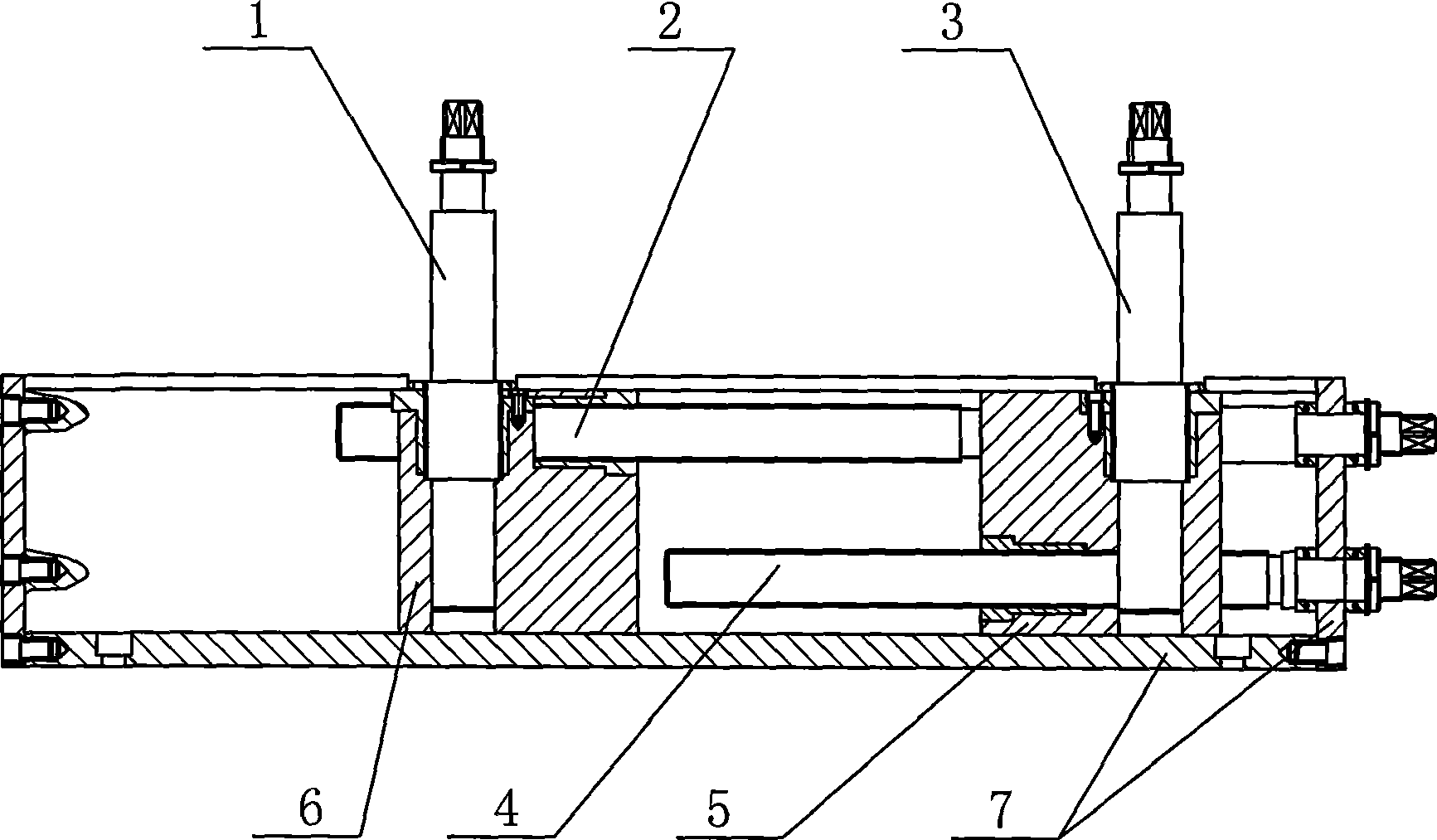
[0008] See figure 1 , figure 2 , the present invention comprises two vertical rollers 1,3, and vertical rollers 1,3 are respectively installed on slide block 6,5, and screw mandrel 2,4 is respectively installed in slide block 6,5, and the wire rod that is positioned at its interior of the slide block of outside The rod goes through the slider on the inside, figure 2 In the middle, the screw rod 2 passes through the slider 5, the screw rods 2 and 4 are respectively connected with the ends of the rack box 7 with bolts, the sliders 6 and 5 are mounted on the track, and the track is set at the bottom of the rack box 7 , the two sides of slide block 6,5 are slidably matched with the two sides of frame box body 7.


PUM


Abstract

The invention relates to a supporting structure for an auxiliary vertical roll, which has the advantages of good rigidity and long service life. The structure comprises two vertical rolls which are installed on two sliders, respectively, a screw mandrel is installed in each slider, the screw mandrel inside the slider positioned on the outer side passes through the slider positioned on the inner side, the screw mandrels are both in bolted connection with the wall slab, and the sliders are embedded in a track. The structure is characterized in that the track is arranged at the bottom of the case body of a frame, the two sides of the sliders are in sliding fit with the two side faces of the case body of the frame, respectively, and the wall slab is the end part of the case body of the frame.

Description

(1) Technical field [0001] The invention relates to the technical field of mechanical processing equipment, in particular to a support structure for auxiliary vertical rollers. (2) Background technology [0002] The role of the auxiliary vertical roller is to further roll the flattened plate to increase the flatness of its surface. At present, the supporting structure of the auxiliary vertical rollers used in the industry includes two vertical rollers arranged side by side. The two vertical rollers are respectively installed on sliders, and the sliders are installed on the slide rails of the foundation. It is connected with the foundation structure through the screw structure. The auxiliary vertical rollers are respectively installed on the two vertical roller shafts, and the rolling dies are respectively installed on the auxiliary vertical rollers. Due to the strong reaction force on the auxiliary roller shaft during the plastic deformation of the plate when the plate is ...

Claims


Application Information

Patent Timeline
Patent Type & Authority Applications(China)
IPC IPC(8): B21D1/02
Inventor 辛亚
Owner 辛亚
Learn More