
Compound apparatus for fumigant

A fumigant and steel cylinder technology, applied in the field of fumigation, can solve the problems of insufficient mixing, component deviation of compound fumigant, difficulty in research and development of compound fumigant, etc., and achieve the effect of convenient sampling and convenient research.

Active Publication Date: 2009-05-13
CHINESE ACAD OF INSPECTION & QUARANTINE +1
View PDF0 Cites 0 Cited by
  • Summary
  • Abstract
  • Description
  • Claims
  • Application Information

AI Technical Summary

Problems solved by technology

For example, Liu Xiaozhen and others studied the disinfection, insecticide and rodent control effects of sulfuryl fluoride and methyl bromide in the container, but they could not use this method to determine the compound formula of the two fumigants (Chinese Journal of Vector Biology and Control, 2005 February, Volume 16, Issue 1, p19~20)
Due to the different molecular weights of various fumigants, when they are compounded together, especially when they are in a liquid state in a pressurized steel cylinder, stratification often occurs, and they cannot be fully mixed, resulting in compounded fumigants sprayed from the pressure vessel. The components of the fumigant have large deviations, which brings difficulties to the development of compound fumigants

Method used


Image

  • Compound apparatus for fumigant

Examples


Embodiment 1

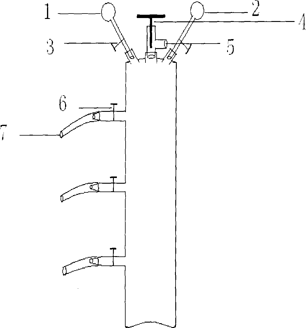
[0015] See figure 1 . An air inlet 5 is drilled in the center of the top of a long columnar steel cylinder made of stainless steel that can withstand 2.0Mpa, and an air inlet valve 4 is welded and installed at the air inlet, and holes are drilled and welded on both sides of the air inlet valve A vacuum gauge 1 and a pressure gauge 2 are installed, and needle valves 3 are respectively provided on the pipelines connecting the vacuum gauge head of the vacuum gauge and the pressure gauge head of the pressure gauge to the steel cylinder; Needle valves 6 are installed by perforation welding, and latex tubes 7 are further connected to the gas outlets of the three needle valves on the cylinder body, which are respectively used as sampling ports for the compound fumigant.

[0016] Utilize the compounding device of fumigant of the present invention to carry out the compounding process of fumigant: open the needle valve 3 of vacuum meter 1, vacuumize the whole device to a certain degree...

Embodiment 2

[0018] The structure of the device is the same as in Example 1, except that the 3 needle valves installed at the middle, upper and lower parts of the steel cylinder body are respectively located in the middle of the steel cylinder body, the middle part of the steel cylinder body and the top of the steel cylinder body, The middle part between the middle of the cylinder body and the bottom of the cylinder body.

[0019] Using this device can better determine the percentage content of different components compounded into the fumigant in the steel cylinder in the liquid phase and gas phase and the uniformity of mixing up and down in the cylinder.


PUM


Abstract

The invention belongs to the technical field of fumigation, and particularly relates to a fumigant compounding device used for preparing compounded fumigant. The fumigant compounding device provided by the invention is characterized in that an air inlet is formed at the top part of a steel bottle in the shape of a long column; an air-inlet valve is mounted at the air inlet; a vacuum meter and a manometer are mounted in drill-holes on two sides of the air-inlet valve respectively; needle valves are arranged on pipelines through which the vacuum meter head of the vacuum meter and the manometer head of the manometer are connected with the steel bottle; needle valves are mounted in drill-holes at the upper, the middle and the lower parts of the bottle body of the steel bottle; and the air outlets of the needle valves in the three positions on the bottle body of the steel bottle are taken as sampling ports for compounding fumigant. When being used for experimental research, the fumigant compounding device provided by the invention can ensure the convenience of sample despite of larger pressure, and is timesaving and safe.

Description

technical field [0001] The invention belongs to the technical field of fumigation, in particular to a compounding device for fumigants used in preparing compound fumigants. Background technique [0002] The currently used fumigants mainly include methyl bromide, ethylene oxide, sulfuryl fluoride, and phosphine. The development of a new fumigant will be very expensive in terms of time and capital investment, and there is a relatively high risk. In addition, single-component fumigants often cannot meet the requirements of production practice. For example, sulfuryl fluoride has good penetrability, kills adults, larvae and rodents of insects, and has low residues. It is a good fumigation agent, but the effect of killing insect eggs is poor, and it has no bactericidal effect. Combining fumigants with different functions or drugs containing other ingredients to give full play to their respective strengths can better serve many aspects such as quarantine treatment, food preservati...

Claims


Application Information

Patent Timeline
IPC IPC(8): B01F13/00B01F15/04B01F3/02B01F3/04B01F23/10
Inventor 张顺合王林李金有慈颖
Owner CHINESE ACAD OF INSPECTION & QUARANTINE
Learn More