
Arc welding robot control system and method thereof

A technology for arc welding and control devices, applied in arc welding equipment, computer control, program control, etc., can solve the problems of inconsistent timing, uneven thickness of weld bead, etc., to reduce the influence of delay, prevent uneven thickness, The effect of correct arc welding

Active Publication Date: 2009-05-06
KOBE STEEL LTD
View PDF1 Cites 20 Cited by
  • Summary
  • Abstract
  • Description
  • Claims
  • Application Information

AI Technical Summary

Problems solved by technology

[0004] In the technologies disclosed in the above two patent documents, the welding conditions such as welding current and the like are changed every time the welding torch performs one cycle of swing, and the welding current command value is different at the left and right ends of the swing, so the problem of uneven thickness of the weld bead occurs
In addition, even if the arc welding robot is equipped with an arc sensor, since the actual welding current is different at the left and right ends of the swing even if there is no deviation on the workpiece, the desired welding line cannot be tracked on the target of the welding rod. offset
In addition, for the swing command, there is a slight delay in the actual swing operation of the welding torch. Due to this delay, the timing of actually performing one-cycle swing of the welding torch and the timing of changing welding conditions such as welding current are inconsistent, so that the left and right ends of the swing are inconsistent. The welding current becomes unequal, resulting in the more advanced the swing cycle, the more uneven the thickness of the weld bead

Method used


Image

  • Arc welding robot control system and method thereof
  • Arc welding robot control system and method thereof
  • Arc welding robot control system and method thereof

Examples


Embodiment Construction

[0023] (Outline of control device)

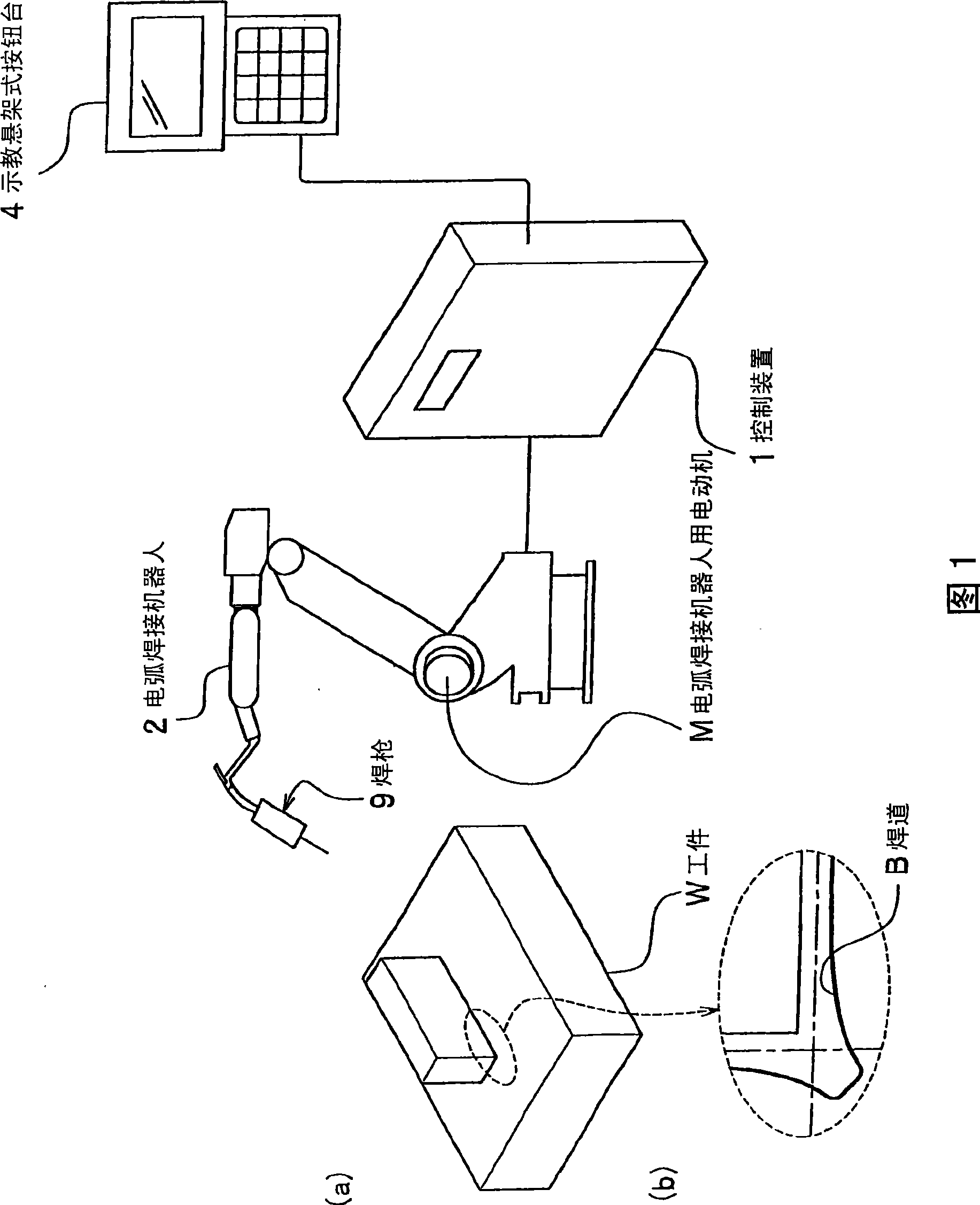
[0024] Hereinafter, embodiments of the present invention will be described in detail with reference to appropriate drawings. The outline of the control device will be described with reference to FIG. 1 . (a) is a configuration diagram showing the outline of an arc welding system including the control device of the present invention, and (b) is an enlarged view of a workpiece and a welding line in the present invention. (a) of FIG. 1 shows a control device (control device of an arc welding robot) 1 , an arc welding robot 2 , a teaching pendant type button table 4 , a welding torch 9 , and a workpiece W. As shown in FIG. In addition, (b) of FIG. 1 shows a workpiece|work W and a weld bead B. As shown in FIG.

[0025] The control device 1 controls the arc welding robot 2 based on commands input from the teaching pendant 4 and the teaching program, and changes the welding conditions of the arc welding robot 2 . In addition, the control device...


PUM


Abstract

An arc welding robot control system of the present invention includes memory devices, controlling devices, a welding condition changing position calculating device (32), a weaving operation controlling device (35) that outputs a signal of completion of one weaving cycle every time when a welding torch completes to perform one weaving cycle of a predetermined movement pattern, a welding condition calculating device (33) for calculating to-be-changed welding conditions, and a welding condition changing device (34) that changes welding conditions of an arc welding robot, based on to-be-changed welding conditions, every time when a signal of completion of one weaving cycle is input. With this configuration, it enables a continuous change of welding conditions and a copying arc welding with high accuracy even in the case in which the arc welding robot performs a weaving operation.

Description

technical field [0001] The invention relates to a control device of an arc welding robot which continuously changes the welding conditions of the arc welding robot. Background technique [0002] Currently, in arc welding using an arc welding robot, in order to change welding conditions such as welding current, welding voltage, welding speed, swing cycle, and swing amplitude step by step, it is necessary to set (teach) multiple welds on the welding line. Condition change position (teaching point), and manually set different welding conditions at each welding condition change position. Therefore, since it is very complicated to manually set the welding conditions at each welding condition change position, a technology for automatically changing the welding conditions has been disclosed (see Japanese Patent Laid-Open No. 61-138470, US Patent No. 6177650). [0003] For example, the technology disclosed in Japanese Patent Application No. 61-138470 is to linearly change the weldi...

Claims


Application Information

Patent Timeline
Patent Type & Authority Applications(China)
IPC IPC(8): B23K9/095B23K9/10B23K9/12G05B19/4093
CPCB23K9/0216B23K9/0953B23K9/12B25J13/00B25J15/0066
Inventor 浅井明彦重吉正之
Owner KOBE STEEL LTD
Learn More