
Knocking type deicer for power transmission line

A technology for transmission lines and deicers, which is applied in the installation of cables, electrical components, overhead installations, etc., and can solve the problems of complex milling equipment, slow milling speed, and inconvenient use

Inactive Publication Date: 2009-04-29
TAIYUAN UNIV OF TECH
View PDF0 Cites 22 Cited by
  • Summary
  • Abstract
  • Description
  • Claims
  • Application Information

AI Technical Summary

Problems solved by technology

[0004] There are many forms of deicing and deicing methods for high-altitude high-voltage cables, such as thermal method, mechanical method, coating method, etc.; the thermal method is to input a large current to the grid to increase the temperature of the high-voltage cable to prevent icing, or Using electric current to heat and melt ice requires large transformer equipment and high power supply current, and it can only be completed in a power failure state, and the energy consumption is huge, and the investment is huge; most of the mechanical methods use milling tools on high-voltage cables. Milling the ice layer, but the milling equipment is complicated, the milling speed is slow, and it is inconvenient to use; the coating method is to coat the high-voltage transmission cable with a chemical agent for deicing and melting ice, so that the cable is not easy to freeze, but the fixation rate of the chemical agent is low , short time limit, easy to fall off, and also affect the input of electric energy, the use effect is not ideal

Method used

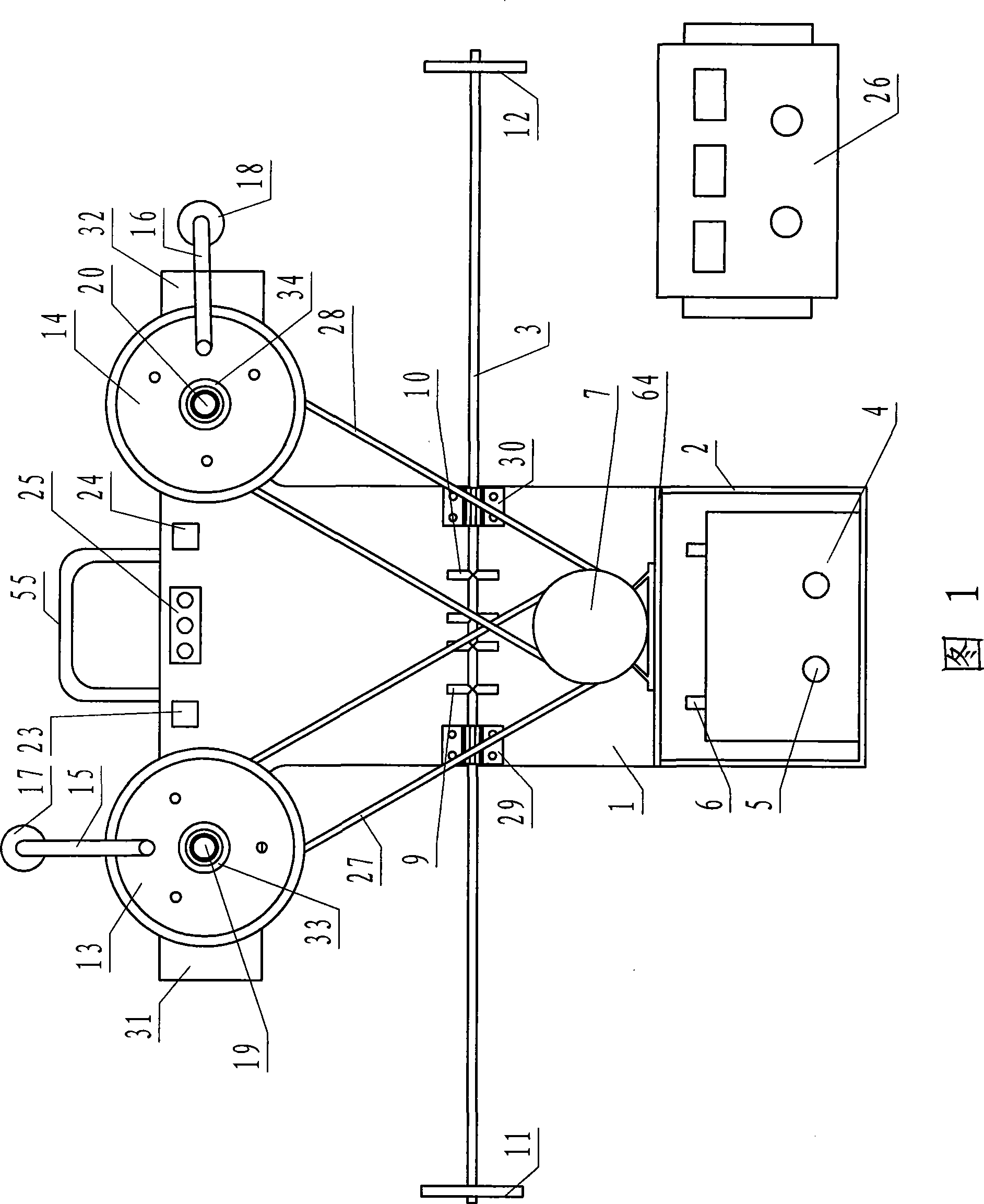
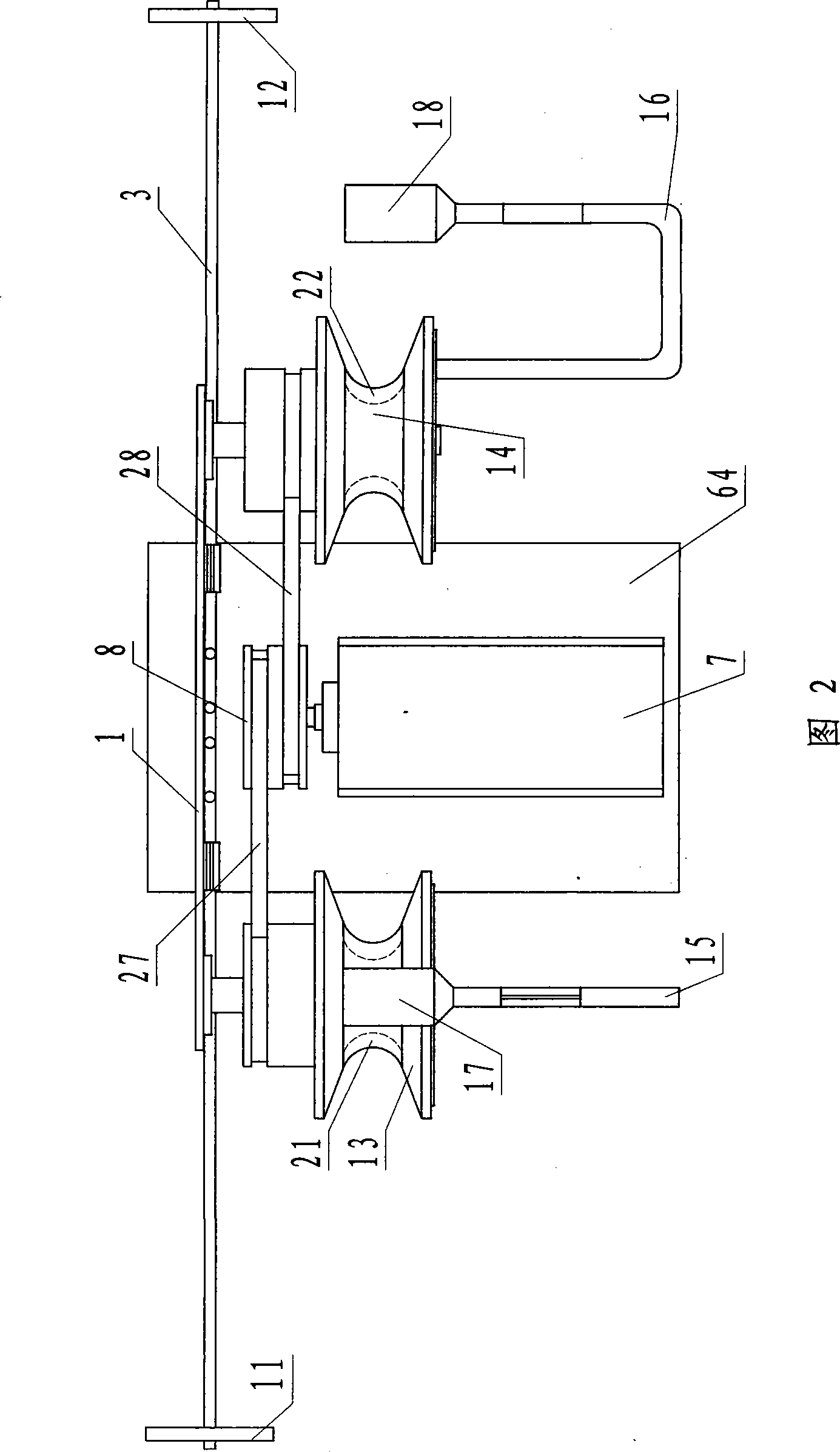
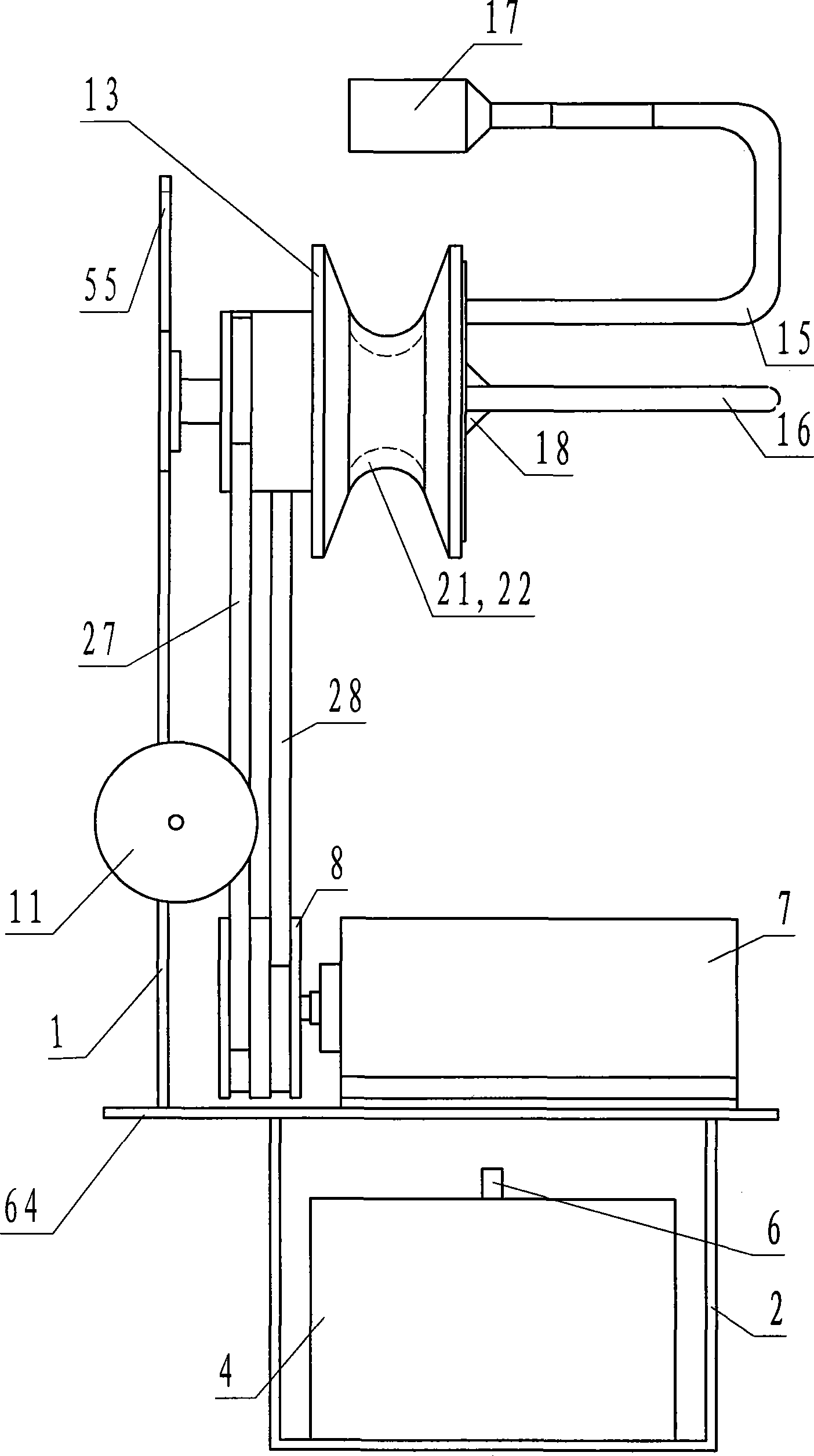

Image

  • Knocking type deicer for power transmission line
  • Knocking type deicer for power transmission line
  • Knocking type deicer for power transmission line

Examples


Embodiment 1

[0041] The method of use is as follows:

[0042] Deicer, remote control receiver, remote control transmitter, sensor, battery power supply, and hot air balloon are all in a quasi-working state;

[0043] Hang the deicer with the hot air balloon;

[0044] Start the hot air balloon and use the control rope to control the hot air balloon;

[0045] Driven by the hot air balloon, the de-icer rises to a specified height;

[0046] Pull the hot air balloon with a rope to drive the left and right wheels of the deicer to align with the power transmission cable, so that the deicer is adsorbed on the cable;

[0047] Operate the hot air balloon and de-icer to loosen the rope, but do not disconnect;

[0048] The ground remote control transmitter instructs the deicer to start working;

[0049] The deicer knocks reciprocatingly to de-icer and automatically reverses direction;

[0050] After the deicing is completed, turn off the deicer motor, tighten the hot air balloon rope, separate the deicer f...


PUM


Abstract

The invention relates to a knocking type ice removal for a transmission cable, which mainly consists of a main board, a transverse plate, a battery case, a battery jar, a direct current motor, a belt pulley, a probe reversing bar, a reversing touch disc, road wheels, a knocking arm, a knocking hammer, a belt, magnets, a sensor, a remote control transmitter, a remote control receiver, a fire balloon and a lead wire, and adopts 24V direct current power supply and a 150W direct current motor, wherein, in each road wheel, each magnet is attached on the transmission cable to prevent beating; the direct current motor drives a left road wheel and a right road wheel to walk left and right; the knocking hammer alternately and circularly knocks ice slush on the transmission cable with the frequency of 3 times / s; the sensor receives ice removing information; the remote control transmitter dictates to complete knocking action; the ice removal adopts a wired controllable fire balloon to be hung and dropped straightly. The device has the advantages of reasonable design, compact structure, safety, stability, reliability, energy conservation, good ice removal effect and high efficiency. By knocking to-and-fro, the ice removing ratio of the ice removal can reach 98 percent, the work efficiency is improved by 2 to 3 times than ice removing by milling, and energy can be saved by 500 times compared with ice removing by transforming voltage heat.

Description

Technical field [0001] The invention relates to a knock-type deicer for power transmission cables, belonging to the technical field of high-altitude and high-voltage power transmission line maintenance equipment. Background technique [0002] With the development of power industry, high-altitude high-voltage transmission lines have become indispensable equipment. The height of high-voltage transmission lines is mostly 15-20 meters, and the voltage of transmission lines is mostly 110KV, 220KV, 330KV, 500KV. my country has built 300KV. , 500KV transmission lines more than 50,000 kilometers. [0003] High-altitude high-voltage transmission lines can operate normally at 5-50℃. In case of special climatic conditions, sudden snowstorms or rain and snow, the temperature fluctuates from 0 to -40℃, and there is often ice formation on transmission cables. It will accumulate more and more, greatly endangering the operational safety of high-voltage lines. The diameter of high-voltage cables ...

Claims


Application Information

Patent Timeline
IPC IPC(8): H02G7/16
Inventor 张超群任正中张振李秀红张明庞荫铭成满庆王春辉
Owner TAIYUAN UNIV OF TECH
Learn More