
Cable system construction method of spatial self-anchored rope-suspension bridge

A self-anchored suspension bridge and construction method technology, applied in the direction of bridges, bridge construction, erection/assembly of bridges, etc., can solve the problems such as excessive angle deviation of drum wires and cable clip lugs, reduce safety factor, etc., and achieve a simple construction method. , to ensure the effect of void ratio

Active Publication Date: 2009-04-29
SHANGHAI MUNICIPAL ENG DESIGN INST GRP
View PDF4 Cites 31 Cited by
  • Summary
  • Abstract
  • Description
  • Claims
  • Application Information

AI Technical Summary

Problems solved by technology

However, the construction of the cable system of the space self-anchored suspension bridge is not feasible, because the main cable is a vertical plane in the empty cable state, but it is a space inclined plane in the bridge state, and there is a process of transformation from plane to space. If the transformation is not good, the cable The angle deviation of the lug plate is too large, and even the main cable appears torsion and wire drum phenomenon, so that the force on the main cable and the cable clamp is uneven, reducing the safety factor and affecting the quality of the project

Method used


Image

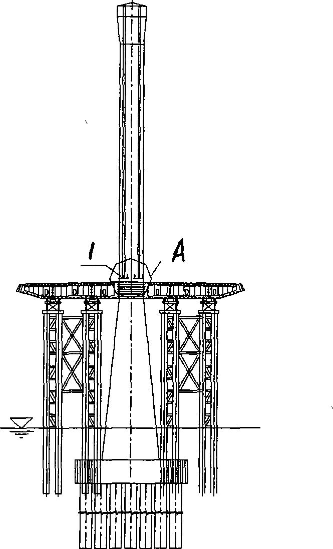
  • Cable system construction method of spatial self-anchored rope-suspension bridge
  • Cable system construction method of spatial self-anchored rope-suspension bridge
  • Cable system construction method of spatial self-anchored rope-suspension bridge

Examples


Embodiment Construction

[0022] The present invention will be further described below in conjunction with the accompanying drawings and examples.

[0023] 1. Set up the catwalk on the vertical plane

[0024] Such as Figure 10 with Figure 11 As shown, the catwalk 1 is composed of catwalk load-bearing cables, beams, handrail cables, surface nets, horizontal wind-resistant stability cables 7, anchor adjustment systems, and the like. Catwalk load-bearing cable 1 can use three-span separation structure. A combined catwalk is set up on both sides. Since the mid-span main cable needs to undergo a space conversion process, two independent catwalks are used for the mid-span catwalk.

[0025] 2. Weaving cables on the vertical plane

[0026] The main cable 2 is set above the catwalk 1, and the main cable unit strands adopt a relatively mature vertical plane erection technology, which is divided into two types: general strand erection and reference strand erection. The main construction steps are: cable s...


PUM


Abstract

The invention discloses a method for constructing a cable system of a spatial self-anchoring type suspension bridge. The method is characterized in that a cat path and a main cable are arranged on the vertical surface to form a hollow cable type; and the completed bridge linearity of the main cable is formed through traversing the main cable and stretching slings. Through the proposal, the method has obvious technical characteristics: 1. the main cable is arranged on the vertical surface and is favorable for braiding the cable; 2. the cable tightening operation is carried out on the vertical surface so as to be favorable for tightening the cable and ensuring the gap rate; and 3. firstly, a temporary inhaul cable is used to traverse the main cable in order that the main cable linearity is close to a completed bridge state; and secondly, the sling is stretched and is favorable for controlling the spatial angle of a cable clip and positioning the sling in a transverse oblique anchor tube. The method has the advantages that the construction method is simple, is favorable for the braiding and molding of the main cable and the spatial positioning of the angles of the cable clip and the slings and realizes the completed bridge linearity of the main cable.

Description

Technical field: [0001] The invention relates to the technical field of bridge construction, in particular to a construction method for a space self-anchored suspension bridge cable system. Background technique: [0002] Since the self-anchored suspension bridge relies on stiffening beams to transmit the horizontal force of the main cable, it must first erect construction supports or trestles in construction, then erect stiffening beams on the supports or trestles, and finally erect main cables and install slings. The adjustment of the sling force enables the self-weight of the stiffening beam to be transmitted to the main cable through the sling, and there is a process of system conversion. [0003] The construction of the cable system of the traditional self-anchored suspension bridge with parallel cable planes is to weave and form the cables on the vertical plane, then install the slings on the vertical plane, and switch the vertical plane system. However, the constructi...

Claims


Application Information

Patent Timeline
IPC IPC(8): E01D21/00
Inventor 沈洋郝维索张剑英臧瑜戴建国
Owner SHANGHAI MUNICIPAL ENG DESIGN INST GRP
Learn More