


Quick Research
Generate reliable direction feasibility study reports for your R&D in just a few steps.

Technical Q&A
Discover and master advanced knowledge NOW. Basics, ideas, possibilities, all at once.

Find Solutions
As an expert in R&D theories, this can generate solutions to your technical problems instantly.

Evaluate Feasibility
Analyze your overall solution with one click, know your potential R&D risks in advance.

Monitor Landscape
Get weekly tech updates, stay abreast of the latest tech innovations and key insights.
Electric dust collector
A dust collector, electric technology, applied in the direction of external electrostatic separator, electrode structure, electrostatic separation, etc., can solve the problem of reduced dust collection efficiency
- Summary
- Abstract
- Description
- Claims
- Application Information
AI Technical Summary
Problems solved by technology
Method used
Image

Examples
Embodiment Construction
[0037] An exemplary embodiment according to the present invention will be described below.
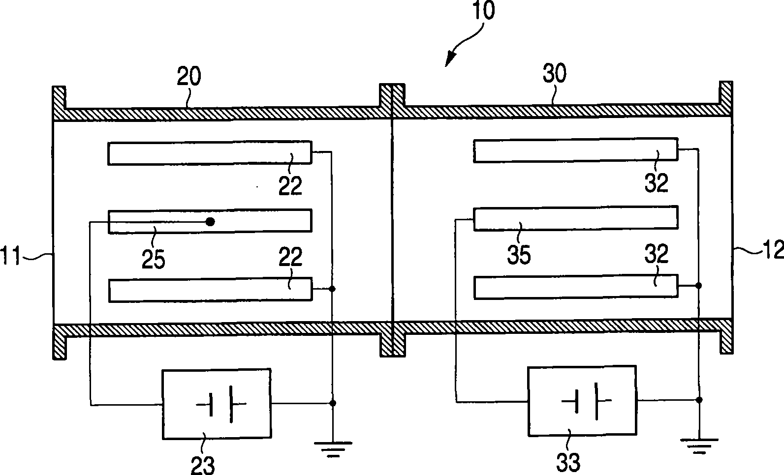
[0038] figure 1 A basic configuration of an electric dust collector according to an embodiment of the present invention is shown.
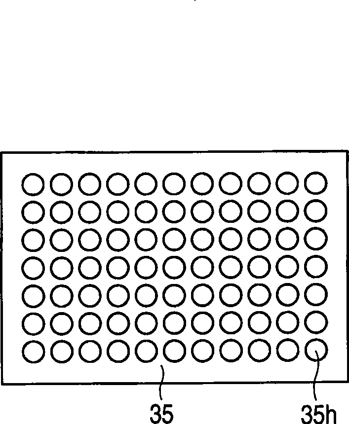
[0039] exist figure 1 In , reference numeral 10 denotes an electric dust collector equipped with a charging unit 20 and a dust collecting unit 30 . In the charging unit 20 , a stainless steel wire discharge electrode 25 and a plate type ground electrode 22 arranged in parallel to each other are arranged inside the body 11 . Corona discharge is generated by applying a high DC voltage between the discharge electrode 25 and the ground electrode 22, whereby air flowing between the two electrodes is ionized and aerosols contained therein are charged to monopolarity. In the dust collecting unit 30, it is formed by applying a high DC voltage between the parallel plate type ground electrode 32 and the high voltage electrode 35 obtained by forming many perfora...
PUM
| Property | Measurement | Unit |
|---|---|---|
| Diameter | aaaaa | aaaaa |
Abstract
Description
Claims
Application Information
 - R&D Engineer
- R&D Manager
- IP Professional
- Industry Leading Data Capabilities
- Powerful AI technology
- Patent DNA Extraction
Browse by: Latest US Patents, China's latest patents, Technical Efficacy Thesaurus, Application Domain, Technology Topic, Popular Technical Reports.
© 2024 PatSnap. All rights reserved.Legal|Privacy policy|Modern Slavery Act Transparency Statement|Sitemap|About US| Contact US: help@patsnap.com