
Coordinates platform for accurately locating three-dimensional laser cutting part

A three-dimensional laser, precise positioning technology, used in laser welding equipment, welding/cutting auxiliary equipment, auxiliary devices, etc., can solve the problems of time-consuming and laborious, unable to obtain satisfactory results, and difficult to accurately position parts, and achieve good portability. , convenient positioning and programming work, convenient and effective positioning effect

Active Publication Date: 2009-04-15
SICHUAN CHENGFEI INTEGRATION TECH
View PDF0 Cites 14 Cited by
  • Summary
  • Abstract
  • Description
  • Claims
  • Application Information

AI Technical Summary

Problems solved by technology

[0003] The above method of positioning and fixing the parts is often affected by the deformation of the parts, and after each positioning, the coordinate system must be adjusted again according to the cut parts. This process often takes a lot of time and is repeated many times.
Moreover, the parts cut out by these two positioning methods will produce relatively large deviations, and satisfactory results cannot be obtained.
When cutting different parts, it is necessary to repeat the positioning process; even if the same part is installed on the machine tool twice, it is time-consuming and laborious to repeat the process of coordinate fitting through feature points
It makes it difficult to accurately locate the part in the machine tool coordinate system, and generate a laser cutting program that can be used directly
How to overcome the above inefficient positioning methods and find a method that can achieve fast and accurate positioning of parts, and at the same time, do not need to reposition during repeated cutting has become an urgent problem in the industry.

Method used


Image

  • Coordinates platform for accurately locating three-dimensional laser cutting part
  • Coordinates platform for accurately locating three-dimensional laser cutting part
  • Coordinates platform for accurately locating three-dimensional laser cutting part

Examples


Embodiment Construction

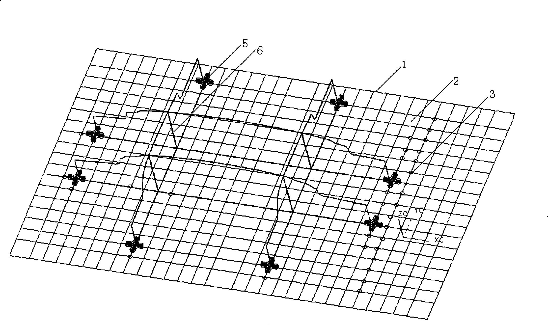
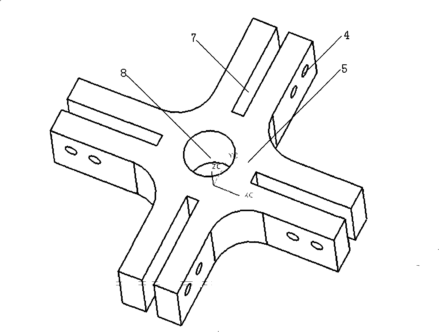
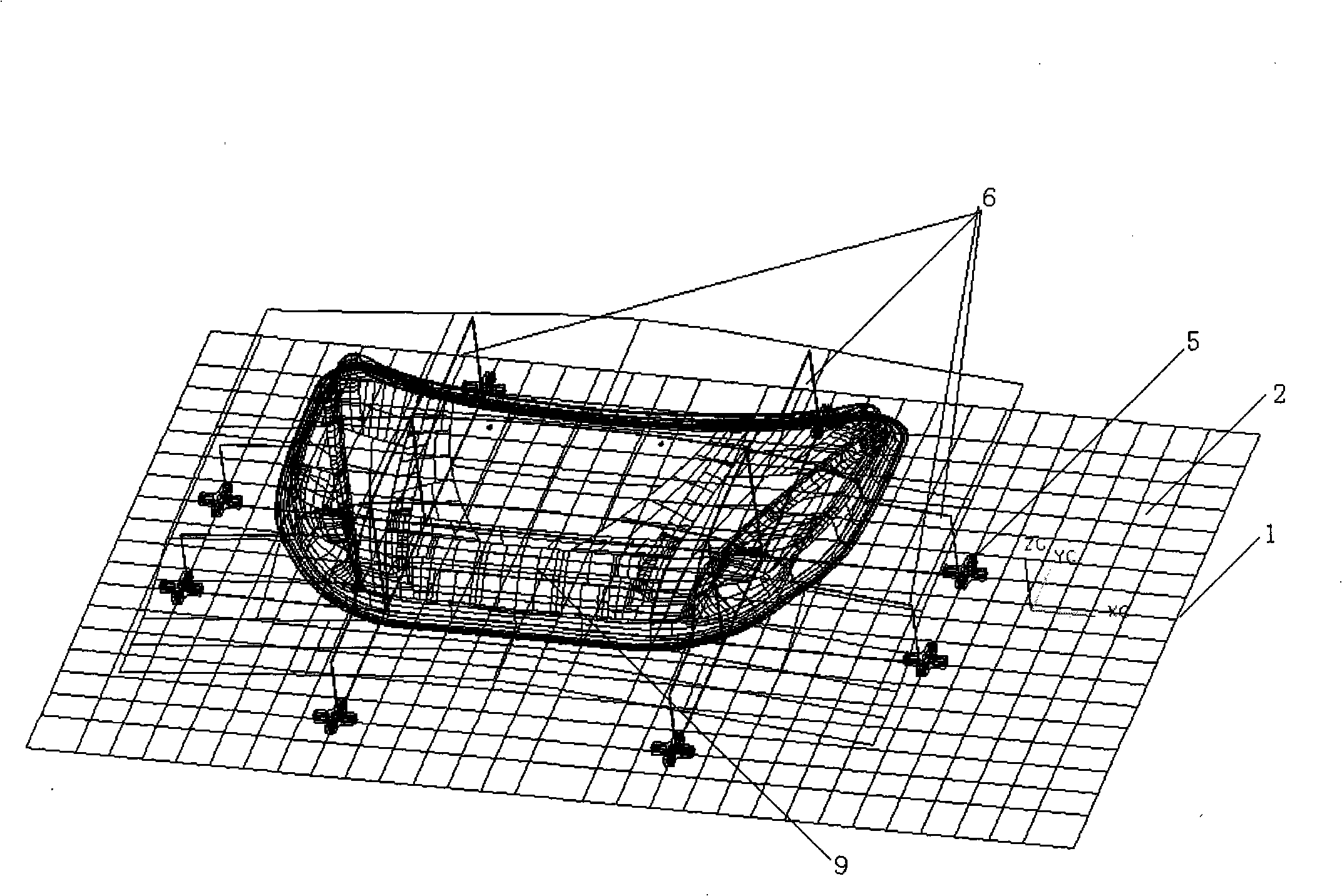
[0011] refer to figure 1 . The positioning base plate 1 shown in the figure can be placed on the TDLC-04R laser cutting machine tool, and its shape is the same as the table top of NTC's TDLC-04R 5-axis three-dimensional laser cutting machine tool. The positioning base plate 1 is fixed on the machine tool table by corresponding several hexagon socket screws. The thickness of the positioning bottom plate is 15mm, and it can be composed of two rigid plates with a total weight of about one ton, which will not affect the operation of the machine tool and are easy to hoist. A rectangular coordinate grid 2 arranged equidistantly is arranged on the table top of the positioning base plate 1 in the length and width direction. The side length of the rectangle of the coordinate grid 2 may be a square with a side length of 50 mm or 100 mm. Positioning threaded holes 3 are formed at the intersection of the coordinate grids, (for a concise drawing, only the arrangement of some holes is sh...


PUM


Abstract

The invention discloses a coordinate platform for accurately positioning three-dimensional laser cut parts, which aims to provide a coordinate platform which is convenient and fast, not only accurately and quickly positions three-dimensional laser cut parts, but also does not need the re-positioning in the repeated cutting, so that the parts can be repeatedly and accurately positioned under the machine coordinate system a plurality of times, and the positioning, programming and cutting work for laser cutting can be conveniently performed. The coordinate platform also comprises a positioning bottom plate, of which the shape is similar to that of the operating platform of the laser cutting machine, and a clip plate for positioning the cut parts. The positioning bottom plate is provided with a rectangular coordinate grid with isometric arrangement; meeting points of the coordinate grid are provided with positioning screw holes; clip plate connectors provided with cross clipping grooves are fixed on the positioning screw holes by fastening bolts; according to the shapes of the cut parts, the clip plate connectors are movably distributed on the meeting points of the coordinate grid, and the clip plate is fixed on the positioning bottom plate by the cross clipping grooves of the clip plate connectors so as to fix and support cut parts.

Description

technical field [0001] The present invention relates to a device for positioning three-dimensional laser cutting parts on a laser cutting machine tool. More specifically, the present invention is a coordinate platform device for precisely positioning laser cutting parts based on the coordinate system of the TDLC-04R laser cutting machine tool. Background technique [0002] At present, the positioning device for laser cutting three-dimensional parts with a laser cutting machine, especially for cutting automobile loading parts, usually has two positioning methods for fixing the parts. One is to select a long sheet of cuttable material according to the spatial geometry of the cutting part, weld it into a plane frame, and then select the positioning point of the part on the strip of the plane frame, and weld the vertical column of the plane frame, the column Distributed on the above planar frame. Then the parts to be cut are fixedly supported on the above-mentioned planar frame...

Claims


Application Information

Patent Timeline
IPC IPC(8): B23K37/04B23K26/42B23K26/70
Inventor 黄犇方建荣余洪
Owner SICHUAN CHENGFEI INTEGRATION TECH
Learn More