
Clamping device

A fastening device and locking clip technology, applied in the direction of threaded fasteners, clothing, connecting components, etc., can solve the problems of low drawing strength, high cost, and great importance.

Inactive Publication Date: 2009-04-08
A RAYMOND & CO
View PDF1 Cites 13 Cited by
  • Summary
  • Abstract
  • Description
  • Claims
  • Application Information

AI Technical Summary

Problems solved by technology

The significance of this defect is all the more significant since the fastening device is used in the final assembly line (which is usually the most expensive)
[0006] In addition, since the pullout strength of a bolt piece is directly related to the mechanical strength of the screw cavity, the pullout strength is relatively low

Method used


Image

  • Clamping device
  • Clamping device
  • Clamping device

Examples


Embodiment Construction

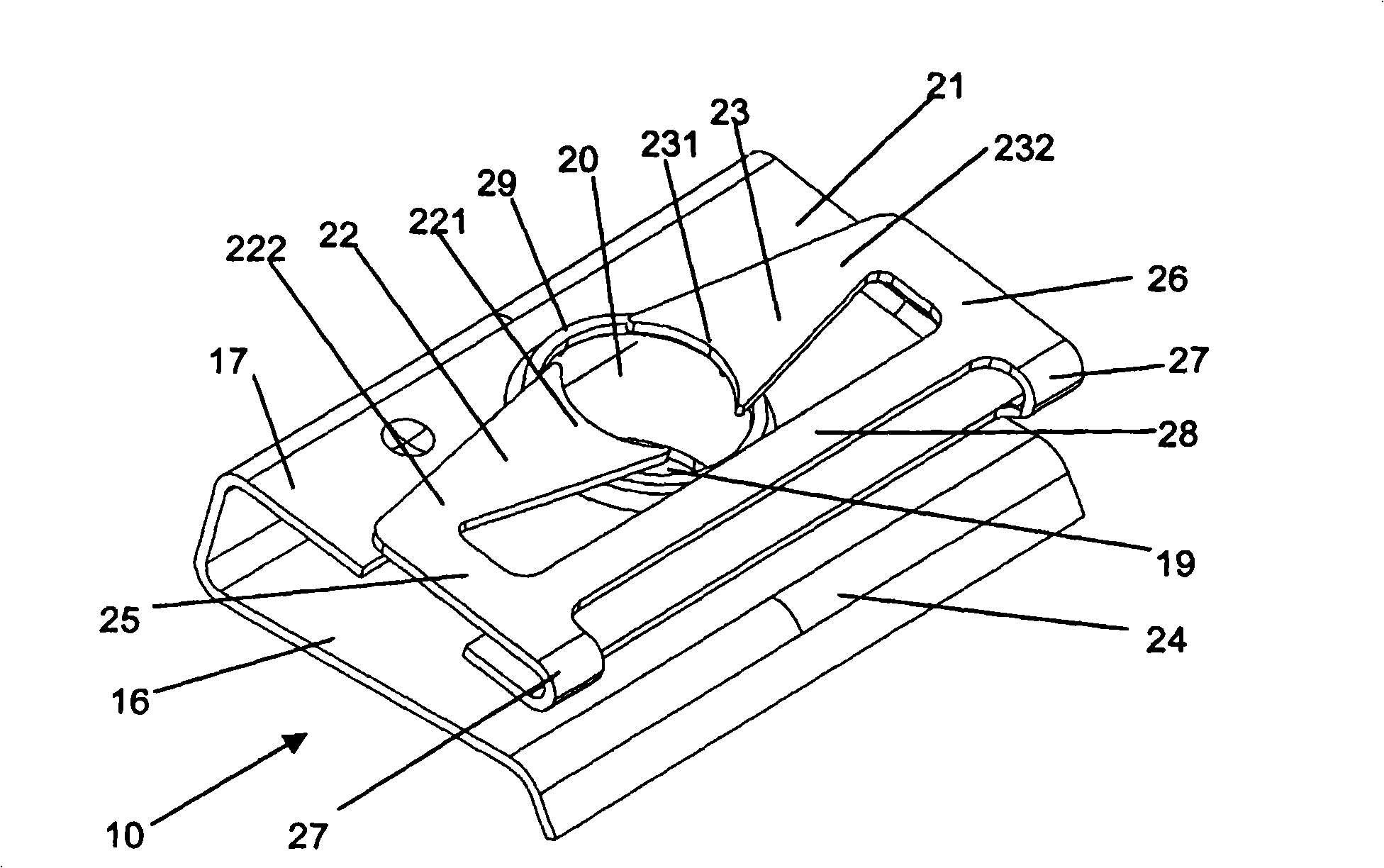
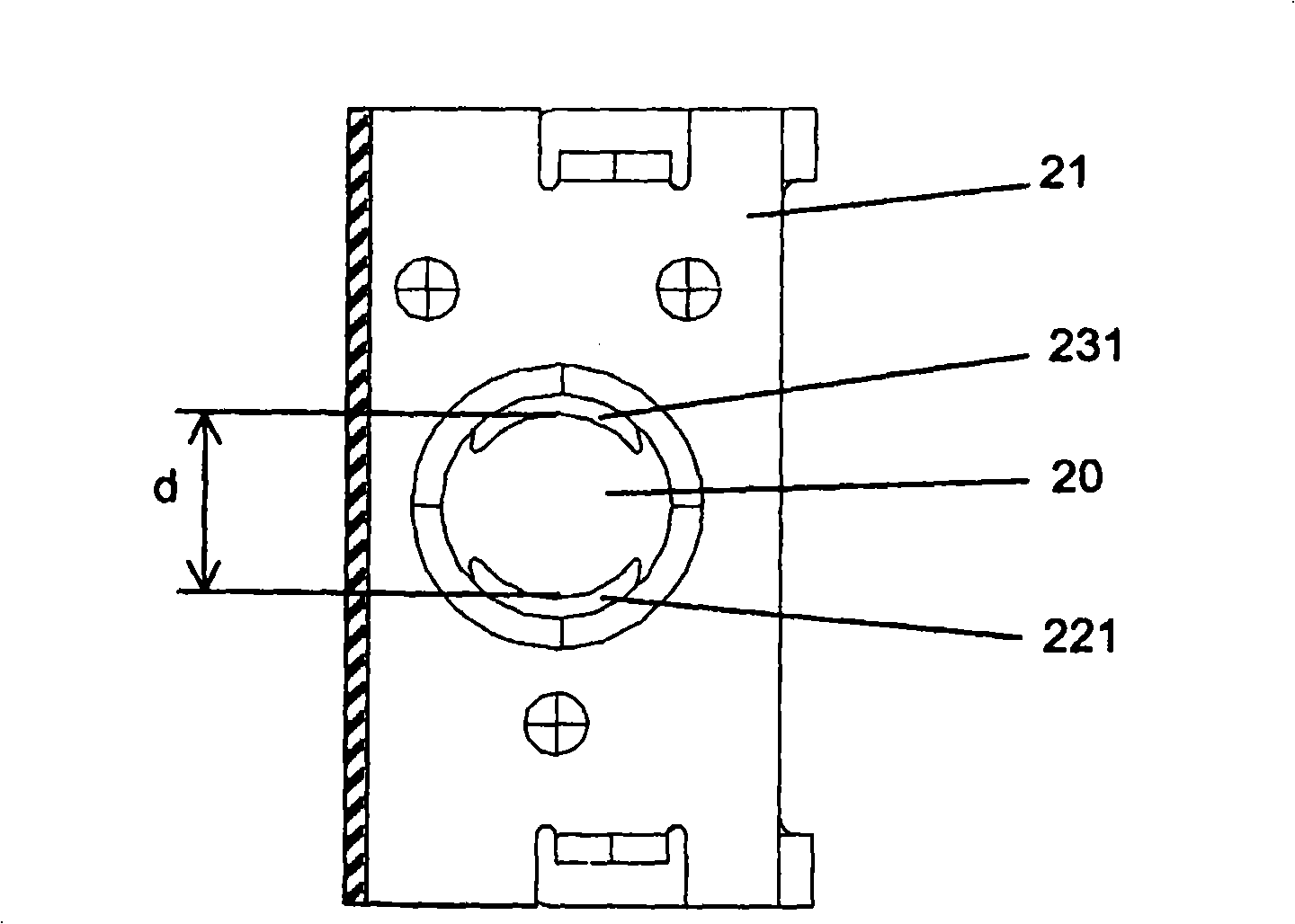
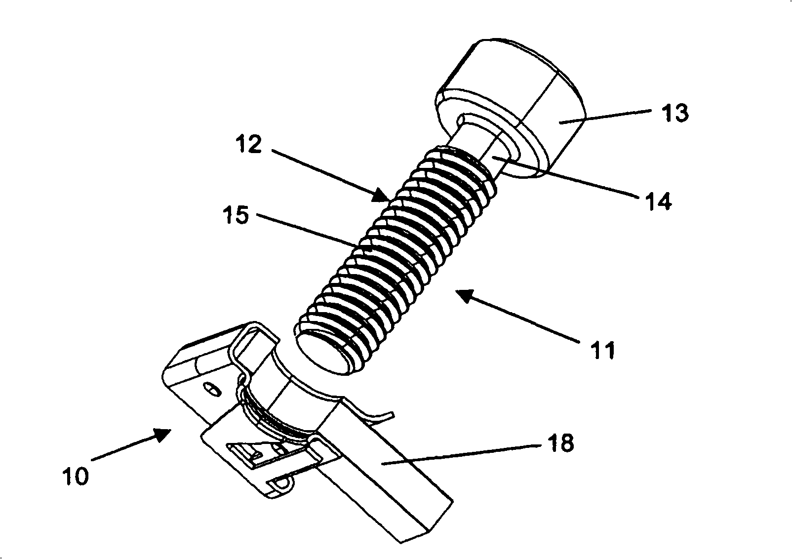
[0018] Figures 1 to 3 A first embodiment of a fastening device according to the invention is shown, comprising a locking clip 10 and a screw part 11 . Bolt member 11 (for example is made of metal, and only in image 3 ) includes a partially threaded rod 12, and a support head 13 at the end called the proximal end. The rod 12 has a smooth upper portion 14 close to the support head 13 and a threaded lower portion 15 extending to the opposite end, referred to as the distal end.

[0019] In this first embodiment, the locking clip 10 is configured as a generally U-shaped cavalier (metal clip) with a first branch 16 and a second branch 17 that are substantially parallel. The locking clip 10 is manufactured by cutting and bending from sheet metal.

[0020] In the following, the fastening device will be described in a specific but non-limiting example of application, such as for assembling planar elements of the type of panels, laths, sheet metal, etc. However, it is obvious that...


PUM


Abstract

The present invention provides a clamping device which comprises: a screw member with a bearing head and a shank equipped with a threaded portion, a retainer (10) comprising a base (21) equipped with a through-hole (20) for the passage of the shank of the screw member, and retaining means supported by the base (21) to lie vertically in line with the through-hole (20), and designed to collaborate with the threaded portion in order axially to immobilize the screw member relative to the retainer (10). The retaining means consist of flexible and elastic tabs (22, 23) arranged such that they converge. Their free ends (221, 231) between them determine a gap (d) smaller than the nominal diameter of the threaded portion (15) so that they automatically engage with the threads of the threaded portion (15) when the shank (12) is inserted axially into the through-hole (20). A burr (29) is arranged at the periphery of the through-hole (20) towards the flexible tabs (22, 23) to form an end stop for the free ends (221, 231) when the shank (12) is axially withdrawn.

Description

technical field [0001] The invention relates to a fastening device comprising: [0002] - a bolt piece having a support head and a shank with a threaded portion, [0003] - a locking clip comprising: a base equipped with a through hole through which the rod of the bolt member passes; and a holder supported by the base so as to be arranged perpendicular to the through hole and capable of cooperating with the threaded portion to Axial fixation between the screw part and the locking clip is achieved. Background technique [0004] Such a device can be used in the assembly of several parts fixed by axial compression, in particular by bolts and nuts. These components are, for example, planar elements of the type plate, lath, sheet metal or the like. We have long known pliers-like nuts, ie U-shaped in general shape and essentially comprising a first branch with a screw cavity connected to a second branch with an opening for the passage of the bolt. An example of this type of fa...

Claims


Application Information

Patent Timeline
Patent Type & Authority Applications(China)
IPC IPC(8): F16B37/04
CPCF16B37/005F16B37/02F16B37/0842Y10T24/44
Inventor 斯特凡娜·热利贝尔
Owner A RAYMOND & CO
Learn More