
Laser gas analyzer and its calibration method

A laser gas and analyzer technology, applied in the measurement of color/spectral characteristics, etc., can solve the problems of instrument measurement error, increased labor intensity, and large consumption, avoiding measurement errors, high sensitivity and accuracy, and low application cost. Effect

Active Publication Date: 2009-04-08
BEIJING BAIF MAIHAK ANALYTICAL INSTR
View PDF0 Cites 41 Cited by
  • Summary
  • Abstract
  • Description
  • Claims
  • Application Information

AI Technical Summary

Problems solved by technology

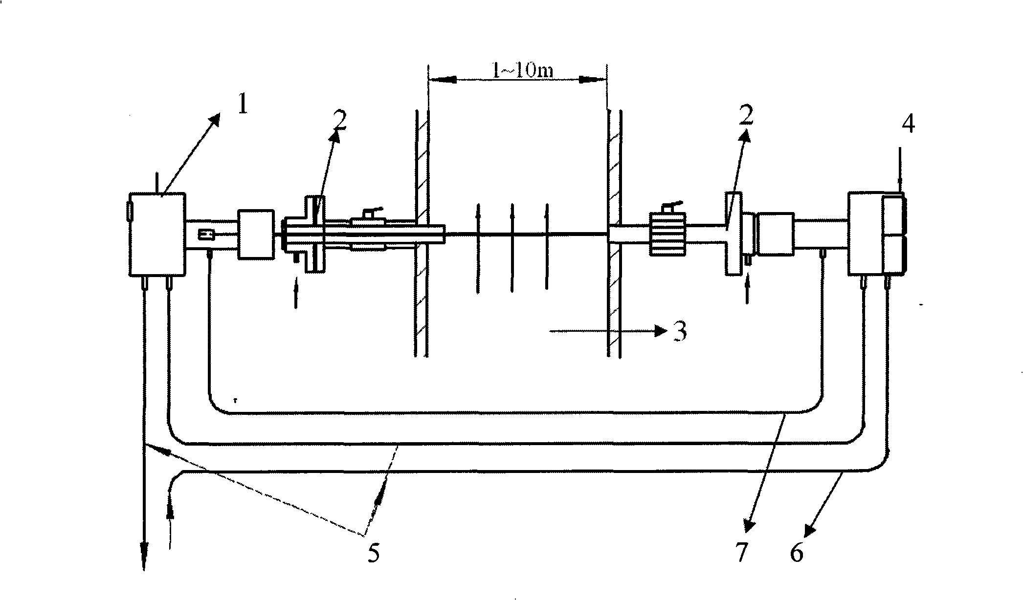
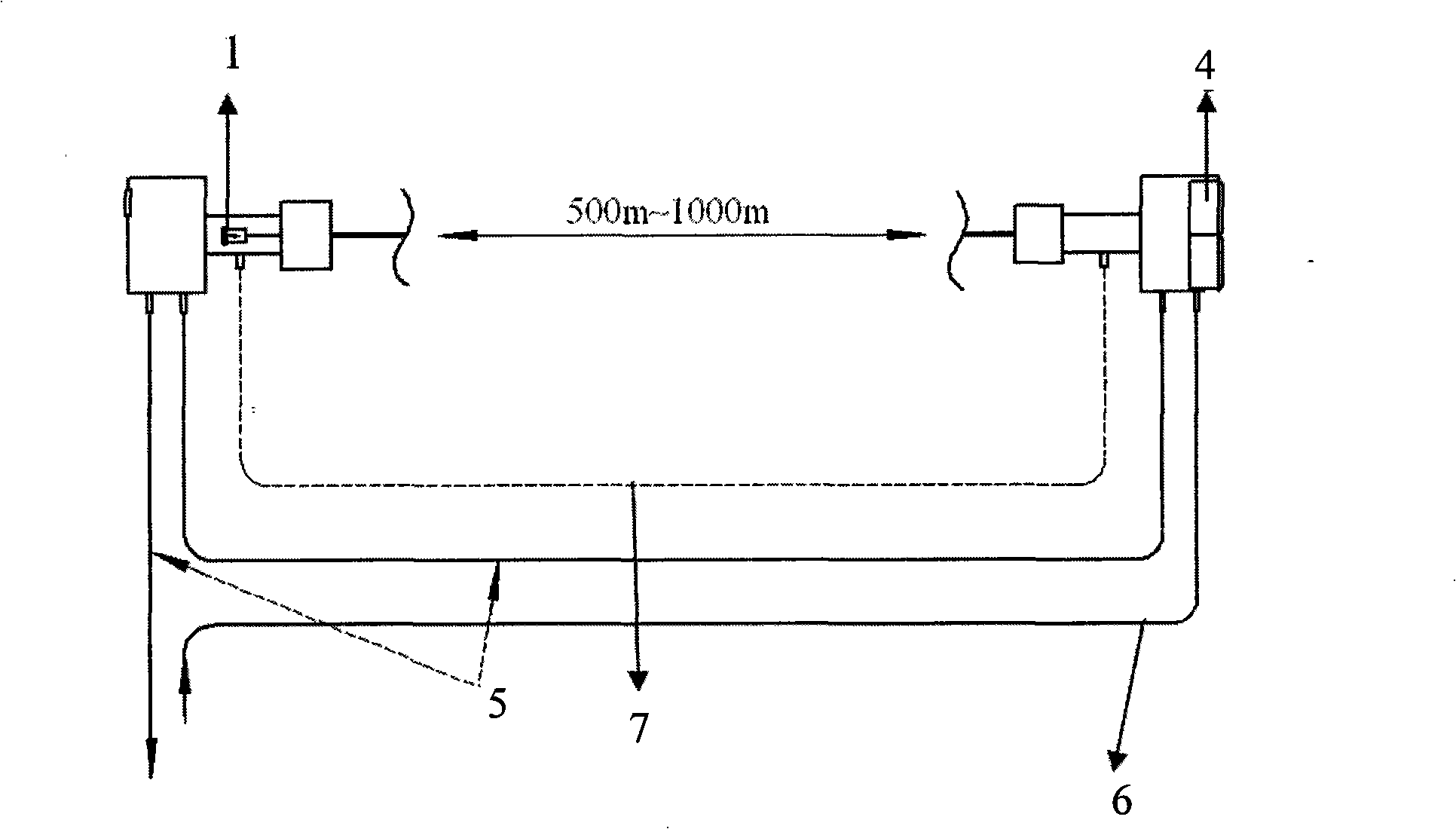
[0008] In the in-situ direct access optical path structure, the flange needs to be fed with purge gas. A further requirement is that this purge gas needs to be almost non-stop during the entire measurement process. Non-stop, so it not only constitutes a consumption point of consumables but also consumes a lot
[0009] The sweeping gas is used to obtain accurate and precise measurement results, because any substances that affect the measurement cannot be mixed into the entire measurement optical path, otherwise it will cause Cause interference, cause instrument measurement error
Although this problem can also be solved by adopting the sealing method of the entire optical path, it is very difficult and costly to implement the sealing process in situ and maintain a long-term effect.
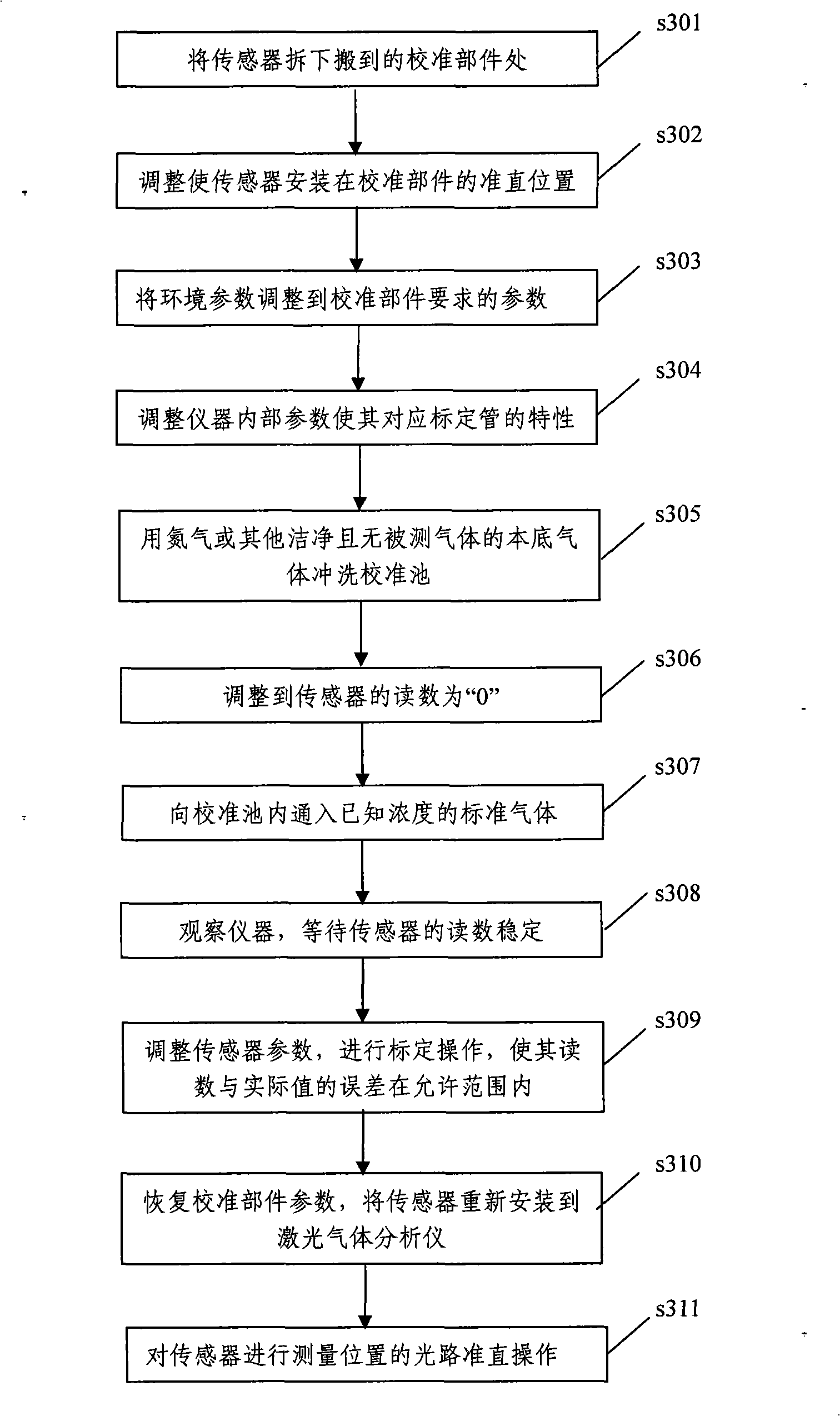
[0010] In addition, the volume of the calibration pool is relatively large, which makes the entire calibration process cumbersome and complicated, increases labor intensity, and consumes a long time and a lot of resources

Method used


Image

  • Laser gas analyzer and its calibration method
  • Laser gas analyzer and its calibration method
  • Laser gas analyzer and its calibration method

Examples


Embodiment

[0068] As shown in Figure 5, it is the optical path structure diagram of the laser gas analyzer of this embodiment. The optical path structure adopts a composite optical path structure, and the composite structure refers to: firstly, the measuring pool 13 adopts reflectors to reflect the measuring beam multiple times to increase the effective measuring optical path. Secondly, in order to obtain the light energy change data at several key points in the light path, the multi-channel beam splitting technology is used for the final photometric calculation. In this embodiment, the light source radiation unit 1 includes a laser light source driving circuit 101 and a semiconductor light source element 102, and the driving circuit 101 provides the current and voltage required by the light source 102 to make it produce a laser beam; in this embodiment, the measuring pool 13 and the reference The pools 12 are all sealed cubes, and the pool body of the measuring pool 13 is equipped with a...


PUM


Abstract

The invention relates to a laser gas analyzer and a calibration method; wherein, the laser gas analyzer comprises a light source radiation unit used for generating semiconductor laser beams, a spectroscopy unit which respectively transmits the generated laser beams to a reference cell which is internally encapsulated by zero gas and gas to be measured with known consistency and a measurement cell where the gas to be measured is pumped into during the measurement process and the zero gas and end gas are respectively pump into during the calibration process, a reference detector which is used for obtaining the energy intensity of the laser beam which passes through the reference cell and positioning the absorption peak wavelength of the gas spectrum, and a measurement detector which is used for measuring the energy intensity of the laser beam which passes through the measurement cell and determining the gas consistency during the measurement process; and the calibration method combines the energy signals of the laser beams obtained by the two detectors with a specific arithmetic to carry out zero calibration and end calibration on the instrument. The laser gas analyzer has the advantages of wide application range, simple calibration operation process, saving time, reducing the production cost and usage cost and the like owning to the characteristics of sealed laser passage and multi-optical passages.

Description

technical field [0001] The invention relates to the field of gas detection by laser technology, in particular to a laser analyzer and a calibration method for analyzing gas concentration by using laser. Background technique [0002] On-line laser gas analyzers that use semiconductor lasers as radiation sources to analyze gases have developed rapidly in the past 10 years. It uses the absorption characteristics of different gases for the corresponding laser spectrum to achieve measurement. This absorption characteristic follows the Lambert-Bill Law (Lambert-Bill Law), which reflects the law of spectral absorption of substances, and the law is expressed as: I=I 0 e- KCL . where I 0 is the initial light energy, I is the light energy received after absorption, L is the length of the light beam passing through the medium, K is the absorption coefficient of the specific substance on the spectrum, and C is the concentration of the component to be detected, that is, C=ln (I 0 / I...

Claims


Application Information

Patent Timeline
Patent Type & Authority Applications(China)
IPC IPC(8): G01N21/39
Inventor 郭肇新姜培刚
Owner BEIJING BAIF MAIHAK ANALYTICAL INSTR
Learn More