Eureka AIR delivers breakthrough ideas for toughest innovation challenges, trusted by R&D personnel around the world.

Apparatus for measuring combustion chamber flue gas temperature by utilizing acoustics

A furnace flue gas and acoustic technology, used in measuring devices, thermometers with physical/chemical changes, thermometers, etc., can solve problems such as large errors, unstable measurement results, and inability to accurately measure for a long time.

Inactive Publication Date: 2009-04-08
NORTH CHINA ELECTRIC POWER UNIV (BAODING)
View PDF0 Cites 34 Cited by
  • Summary
  • Abstract
  • Description
  • Claims
  • Application Information

AI Technical Summary

Problems solved by technology

A complex cooling device is required, and it can only be used to prevent the pipeline from overheating for short-term measurement when the boiler is ignited. When the temperature exceeds 540°C, the probe will automatically exit, and real-time measurement when the boiler is running cannot be realized.
For portable temperature measurement equipment such as infrared temperature measurement, the engineering community generally believes that its measurement results are unstable and the error is too large, so it is difficult to apply to high-temperature flue gas measurement
Recently, there has been a technology based on CCD image inversion of temperature, but due to the problem that the camera is prone to fouling due to fly ash in the furnace, it cannot be measured accurately for a long time
Therefore, there is no technology and device that can realize long-term stable, accurate and real-time online monitoring of furnace flue gas temperature in China.

Method used


Image

  • Apparatus for measuring combustion chamber flue gas temperature by utilizing acoustics

Examples


Embodiment Construction

[0016] The present invention provides a device for measuring the flue gas temperature of a furnace by means of acoustics, and the present invention will be further described below through the description of the drawings and specific implementation methods.

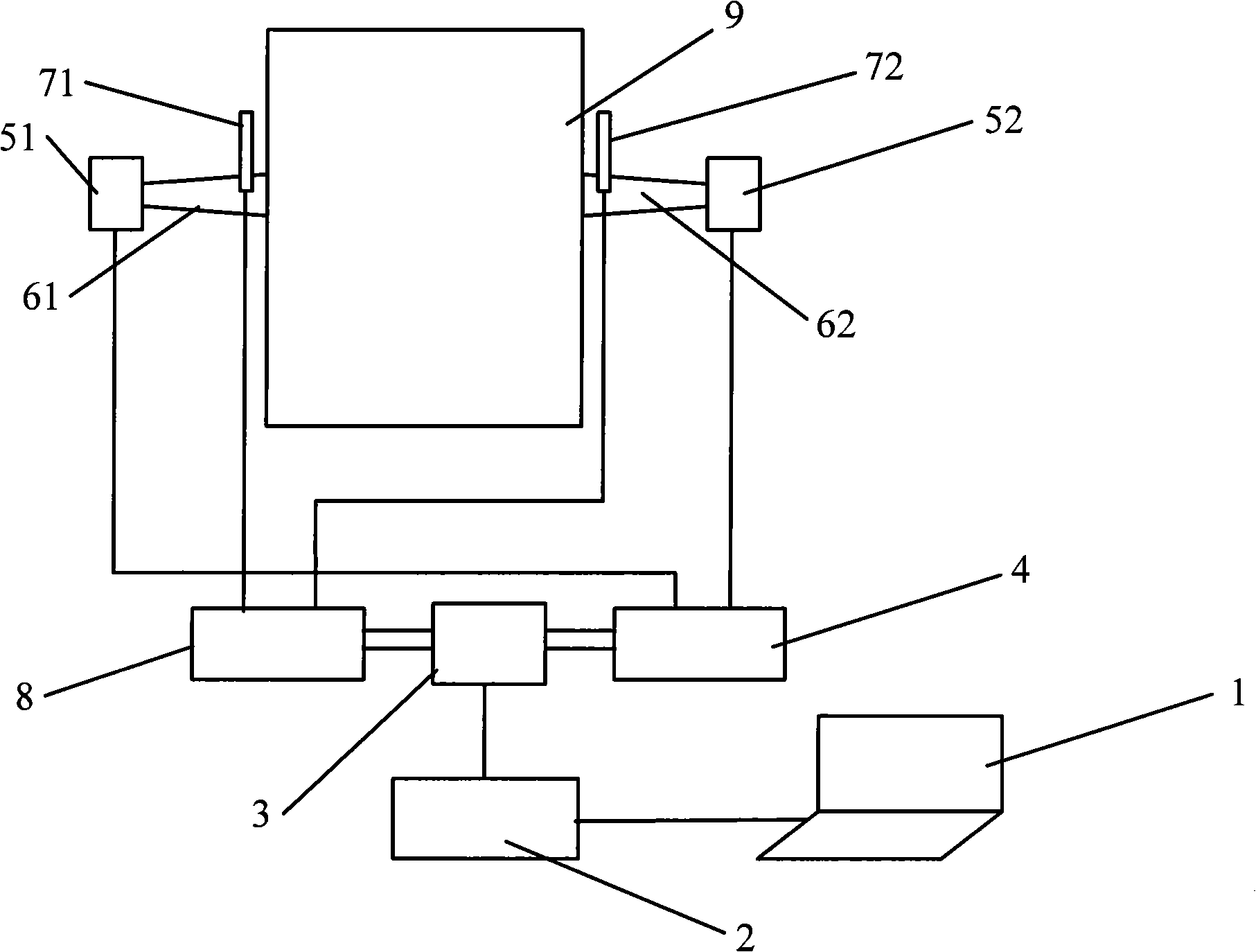
[0017] figure 1 It is a structural schematic diagram of the flue gas temperature measuring device of the present invention. The left acoustic waveguide 61 and the right acoustic waveguide 62 are respectively installed at symmetrical positions above the middle part of the furnace wall side wall of the furnace 9. The left acoustic waveguide 61 and the right acoustic waveguide 62 adopt conical horns, and the acoustic impedance changes uniformly near the cutoff frequency and has strong directivity. , to facilitate the rectilinear propagation of sound waves; the end of the left acoustic waveguide 61 is connected to the left dynamic speaker 51, the left enhanced microphone 71 is installed on the upper end of the left acoustic wa...


PUM


Abstract

The invention belongs to the high-temperature off-gas temperature measurement technical field, in particular to an apparatus adopting the acoustics to measure the temperature of off-gas in a hearth. A set of sound-wave transceiver comprising a sound-wave duct, an electric speaker and a reinforced microphone is respectively arranged onto the symmetrical positions of the wall on two sides of the boiler hearth; the electric speakers send out sound signals which are simultaneously received by the reinforced microphone of the same side or the opposite side and are converted into voltage signals; after the voltage signals pass through a signal regulator, the signals are input through a cable into a double-channel data collecting card to be converted into digital signals; then a cross correlation is adopted for analysis to obtain the time-of-flight of sound wave and finally the computer and software are adopted to figure out the temperature of off-gas. The work of the apparatus is not limited by the high-temperature, dusts, corrosion and onflow and the like. complicated and rigid conditions in the boiler and the apparatus is provided with the features of non-insertion style, accuracy, real-time and portable measurement; and the apparatus can replace the traditional hearth high-temperature probes and can in time judge the combustion condition of the boiler for regulation and control.

Description

technical field [0001] The invention belongs to the technical field of high-temperature flue gas temperature measurement, in particular to a device for measuring the temperature of flue gas in a furnace by acoustics. Background technique [0002] In large-scale coal-fired and oil-fired boilers, such as thermal power plant boilers, steelmaking blast furnaces, cement rotary kilns, cokers and other high-temperature equipment, the measurement of flue gas temperature in the furnace is directly related to the stability and optimization of combustion, which is very important for the safety of equipment. , Economic operation is of great significance. In the past, due to the limitations of complex and harsh environments such as high temperature, dust, corrosion, and turbulence in the furnace, the temperature of the boiler flue gas is mostly obtained by thermal calculation based on heat balance. This indirect method through calculation needs to collect a large amount of temperature a...

Claims


Application Information

Patent Timeline
Patent Type & Authority Applications(China)
IPC IPC(8): G01K11/24
Inventor 沈国清安连锁杨祥良奚正稳
Owner NORTH CHINA ELECTRIC POWER UNIV (BAODING)
Why Eureka
Eureka Blog
Learn More