Control circuit for power factor corrector

A power factor correction and control circuit technology, applied in the direction of output power conversion devices, electrical components, sustainable manufacturing/processing, etc., can solve the problems of total harmonic distortion increase, power factor reduction, input current waveform distortion, etc., to achieve The effect of reducing total harmonic distortion and improving power factor

Inactive Publication Date: 2009-04-01
SYST GEN
View PDF0 Cites 11 Cited by
  • Summary
  • Abstract
  • Description
  • Claims
  • Application Information

AI Technical Summary

Problems solved by technology

Such a design method will cause the input inductor current I LIN Every half power cycle, corresponding to the rectified voltage V REC At the valley of the voltage, the switching signal V G The duty cycle is too small to switch, which makes the input inductance L IN Unable to charge and discharge
During this period, the input inductor current I cannot be output LIN , resulting in input current waveform distortion, power factor reduction and total harmonic distortion increase

Method used


Image

  • Control circuit for power factor corrector
  • Control circuit for power factor corrector
  • Control circuit for power factor corrector

Examples


Embodiment Construction

[0043] In order to enable the examiner to have a further understanding and understanding of the structural features and achieved effects of the present invention, the preferred embodiments and accompanying drawings are used for detailed descriptions, as follows:

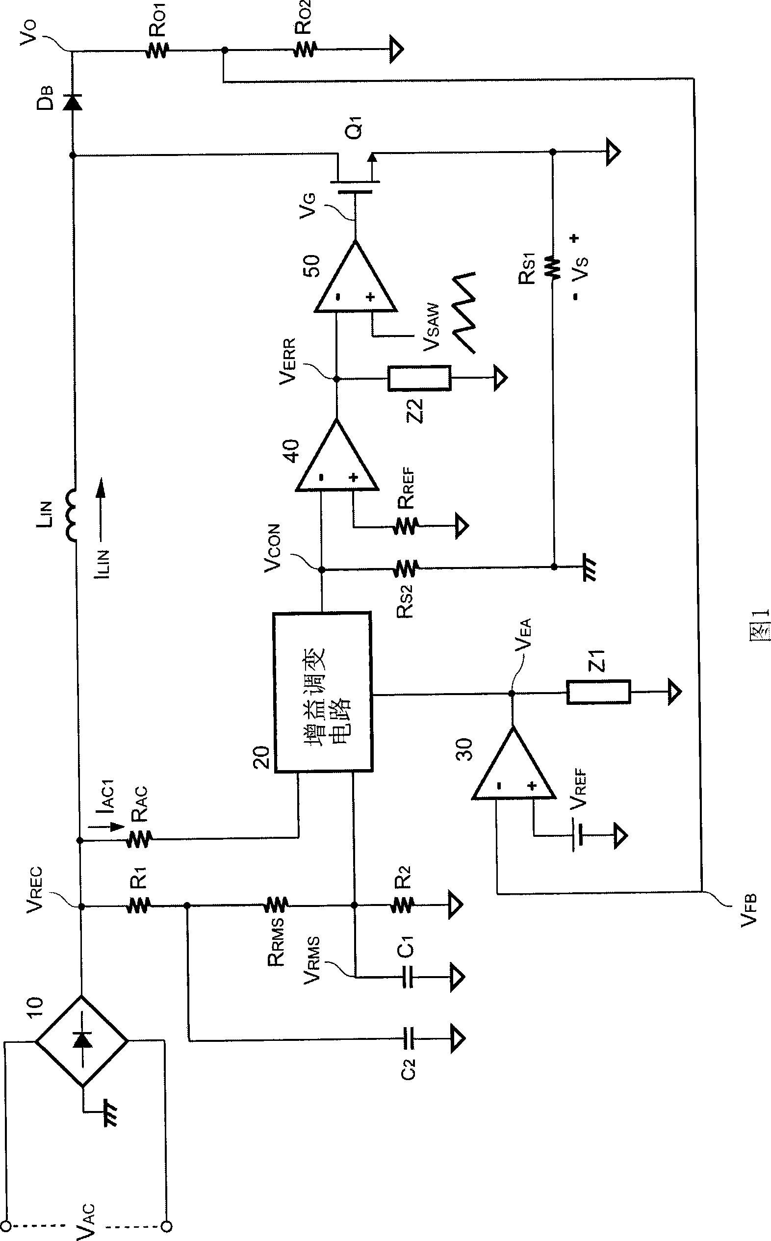
[0044] Please refer to FIG. 3 , which is a circuit diagram of a preferred embodiment of the present invention applied to a power factor corrector. As shown in the figure, an AC input voltage V AC The input is rectified by the bridge rectifier 10 and then converted into a rectified voltage V REC , the rectified voltage V REC via the input inductance L IN , Power switch Q 1 , and the rectifier D B rectification to produce an output voltage V O . The output voltage V O is for a higher DC voltage, and the power switch Q 1 The switching is through the switching signal V output by a control circuit G controlled by. The control circuit through the resistor R O1 and R O2 Coupled to the output terminal of the powe...


PUM


Abstract

The invention provides a control circuit which is used in a power factor corrector. The power factor corrector transforms an AC input voltage after being rectified to a rectifying voltage; the control circuit outputs a switching signal so as to control a power switch; the control circuit comprises a voltage division filtration circuit which produces an input current signal and an effective value voltage signal after voltage division and filtration for the rectifying voltage according to an effective voltage signal, the wave shape of the input current signal is the same as the wave shape of the rectifying voltage, and a DC level is improved. The control circuit also comprises a gain modulation circuit which produces a control signal according to the input circuit signal, the effective value voltage signal and an error signal, the error signal is produced by one output terminal of the power factor corrector, and the control circuit further comprises a switching circuit which is coupled with the gain modulation circuit and outputs the switching signals according to the control signal and a sawtooth wave signal, wherein, the input current signal with DC level can improve the power factor and lower the total harmonic distortion.

Description

technical field [0001] The invention relates to power control technology, in particular to a control circuit applied to power factor control. Background technique [0002] Many power converters apply a power factor correction (Power Factor Correction, PFC) circuit to correct the input current at the power supply terminal, please refer to FIG. 1 , which is a prior art power factor correction device. The power factor corrector operates in a boost topology with continuous or discontinuous inductor current mode and operates at a fixed or variable switching frequency to convert the AC input voltage V AC After being rectified by the bridge rectifier 10, it is converted into a rectified voltage V REC , rectified voltage V REC via an input inductor L IN , a power switch Q 1 , and a rectifier D B rectification to produce an output voltage V O . output voltage V O is for a higher DC voltage, while the power switch Q 1 The switching is through a switching signal V output by a ...

Claims


Application Information

Patent Timeline
Patent Type & Authority Applications(China)
IPC IPC(8): H02M1/42
CPCY02B70/126Y02B70/10Y02P80/10
Inventor 陈振松徐乾尊江定达黄少军
Owner SYST GEN
Why Eureka
Try Eureka