Electric driving fully variable valve actuator for air-powered engine

A pneumatic engine, electric drive technology, applied in the direction of engine components, machines/engines, mechanical equipment, etc., can solve the problem that the rotary valve air intake device of the pneumatic engine cannot be realized, reduce the throttling loss, realize the time adjustment, overcome the The effect of high switching frequency

Inactive Publication Date: 2009-04-01
ZHEJIANG UNIV
View PDF2 Cites 4 Cited by
  • Summary
  • Abstract
  • Description
  • Claims
  • Application Information

AI Technical Summary

Problems solved by technology

Neither the traditional camshaft driven valve system nor the pneumatic engine rotary valve intake device proposed by Chinese patent number [02160723.0] can realize this function

Method used


Image

  • Electric driving fully variable valve actuator for air-powered engine
  • Electric driving fully variable valve actuator for air-powered engine
  • Electric driving fully variable valve actuator for air-powered engine

Examples


Embodiment Construction

[0020] The present invention will be described in detail below in conjunction with the accompanying drawings.

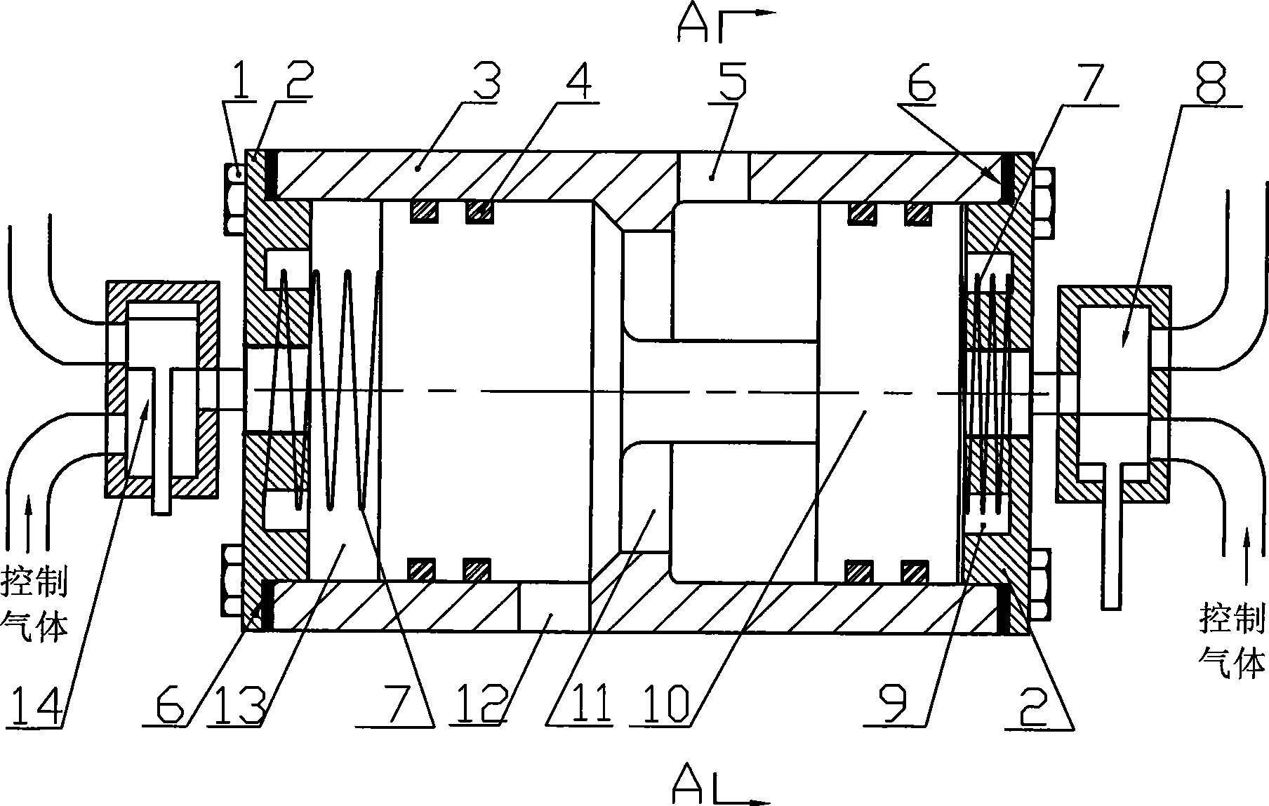
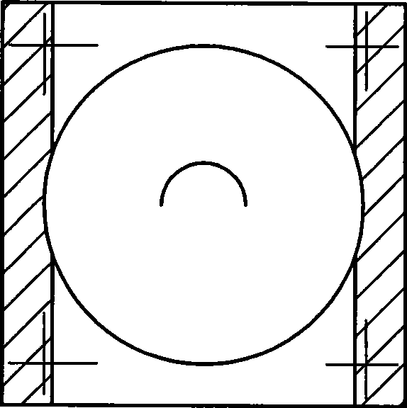
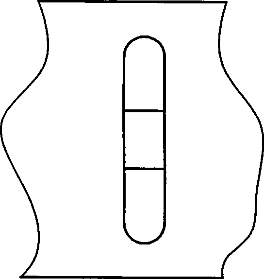
[0021] In this embodiment, the electric drive of the pneumatic engine fully variable valve mechanism is as follows: figure 1 As shown, on both sides of the cuboid-shaped valve body 3, there are narrow and long waist-shaped hole-shaped air inlets 5 and air outlets 12; the valve core 10 is installed in the inner cavity of the valve body 3 and can move back and forth left and right, with two cylinders The two ends of the valve core 10 divide the inside of the valve body 3 into three chambers, the left chamber 13, the middle chamber 11 and the right chamber 9. Several sealing rings 4 are installed on the two ends of the valve core 10 to complete the sealing between the left chamber 13 and the middle chamber 11 and the right chamber 9 and the middle chamber 11; the inner wall of the valve body 3 is in the middle There is an annular boss at the position of the chamber 11;...


PUM


Abstract

The invention relates to an intake and exhaust valve mechanism of an engine, which aims at providing a fully variable valve mechanism that can continuously regulate the valve timing and lifting of an air-actuating engine by controlling the power supply connection and disconnection of an electromagnetic valve. The mechanism comprises a valve body, a valve core and valve-body end caps arranged at the two ends of the valve body; the valve core is provided with two end parts and a connecting part arranged between the two end parts; the two end parts of the valve core divide the interior of the valve body into three chambers; a limit spring is arranged between the two end parts of the valve body and the valve-body end caps respectively; a two-position three-way electromagnetic valve that is communicated with the air and controls gas and the chambers of the valve body is arranged on the valve-body end caps; and the two sides of the valve body are respectively provided with an air inlet and an air outlet. The valve realizes the decoupling of movement of the valve of the air-actuating engine and the rotating speed of a crankshaft, reduces the air intake throttling loss, can realize braking energy recycling in the working mode of an air compressor and adjust the braking strength quite conveniently during the recycling process, and has fast responding speed of the opening and closing of the main valve core and simple and compact structure.

Description

technical field [0001] The invention relates to an intake and exhaust valve mechanism for an engine. More specifically, the invention relates to a fully variable valve mechanism that can continuously adjust the valve timing and lift of the air engine by controlling the on-off time of the solenoid valve. valve train. Background technique [0002] The continuous soaring of fuel prices and the increasing environmental pollution caused by fuel vehicles have made countries all over the world step up the research and development of new energy vehicles. The pneumatic engine uses compressed air and liquid nitrogen as the working medium, does not need to consume oil during the work process, and can achieve zero emissions, which is a development direction. The characteristic of high-pressure air intake of pneumatic engine makes it impossible to continue to use the camshaft-valve type valve train of traditional internal combustion engine. The main power source of the gas engine comes...

Claims


Application Information

Patent Timeline
Patent Type & Authority Applications(China)
IPC IPC(8): F01L9/04
Inventor 陈平录俞小莉许静胡军强聂相虹
Owner ZHEJIANG UNIV
Why Eureka
Try Eureka