
Stock-cutter

A cutting machine and frame technology, which is applied in the direction of shearing devices, shearing machine accessories, shearing machine equipment, etc., can solve the problems of low penetration rate, complicated equipment, high cost, etc.

Inactive Publication Date: 2009-04-01
肖荣
View PDF0 Cites 8 Cited by
  • Summary
  • Abstract
  • Description
  • Claims
  • Application Information

AI Technical Summary

Problems solved by technology

[0002] In the existing cold roll forming process, high-power shearing machines are usually used to shear steel plates, and high-power shearing machines mostly cut steel plates of 5-10 mm, and the equipment is complex, costly, and popular in the market. lower

Method used


Image

  • Stock-cutter
  • Stock-cutter

Examples


Embodiment Construction

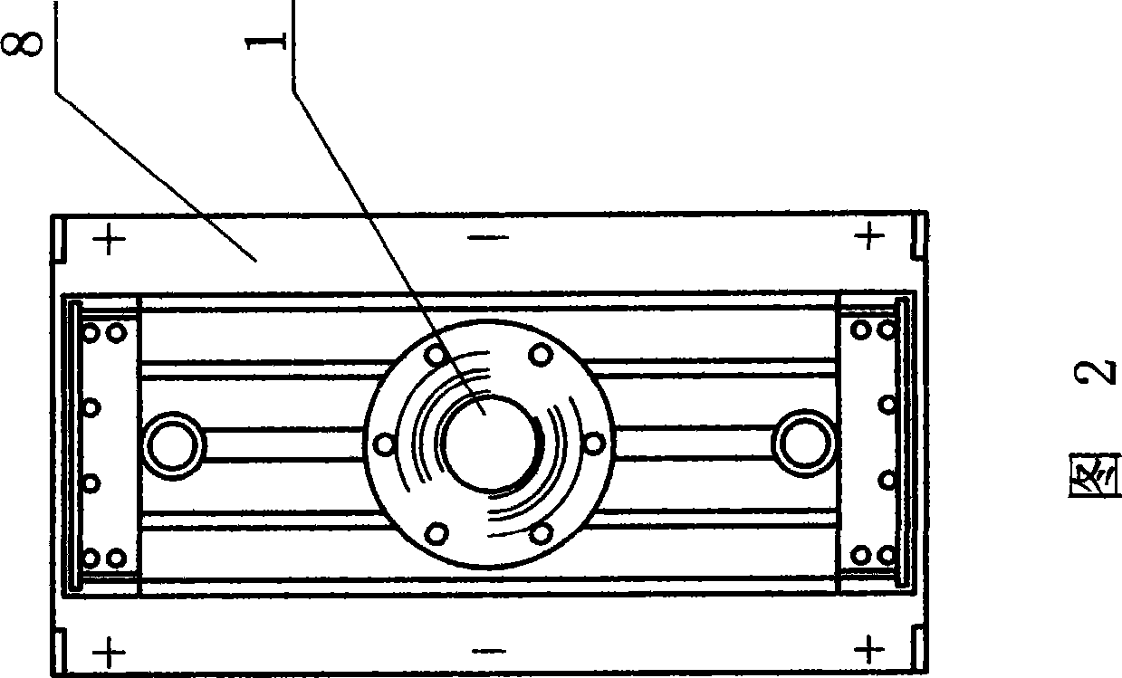
[0009] See Fig. 1, Fig. 2, the present invention comprises frame 8, and hydraulic cylinder 1 is installed on frame 8, and the piston rod of hydraulic cylinder 1 connects slide block 10, and slide block 10 is embedded in guide rail 2, and guide rail 2 is installed in frame 8 , the lower end of the slide block 10 is equipped with an upper blade 9, corresponding to the shearing direction of the upper blade 9, the frame 8 is equipped with a lower blade 7, and at the side of the upper blade 9, the slide block 10 is equipped with a spring compression structure, The spring compression structure includes a guide post 3, which is installed on the slider 10. The guide post 3 is covered with a spring 5, and the spring 5 is in a compressed state. 6. The lower end surface of the pressing block 6 is lower than the height of the upper blade 9 .


PUM


Abstract

The invention relates to a stock cutter which has simple structure and low cost. The stock cutter is suitable for cutting and processing a medium and thin slab and has higher market popularizing rate. The stock cutter comprises a stander and is characterized in that a hydraulic cylinder is arranged on the stander, a piston rod of the hydraulic cylinder is connected with a slipper block that is embedded on a guide way which is arranged on the stander, an upper blade is arranged at the lower end of the slipper block, a lower blade is arranged on the stander corresponding to the cutting direction of the upper blade and the slipper block is provided with a spring compressing mechanism at the lateral part of the upper blade.

Description

(1) Technical field [0001] The invention relates to parts of a cold-bending forming unit, in particular to a cutting machine. (2) Background technology [0002] In the existing cold roll forming process, high-power shearing machines are usually used to shear steel plates, and high-power shearing machines mostly cut steel plates of 5-10 mm, and the equipment is complex, costly, and popular in the market. lower. (3) Contents of the invention [0003] In view of the above problems, the present invention provides a cutting machine, which has a reduced structure and low cost, is suitable for shearing processing of middle thin plates, and has a high penetration rate in the market. [0004] Its technical solution is: it includes a frame, which is characterized in that: a hydraulic cylinder is installed on the frame, the piston rod of the hydraulic cylinder is connected to a slider, and the slider is embedded in a guide rail, and the guide rail is installed on the machine. frame...

Claims


Application Information

Patent Timeline
IPC IPC(8): B23D15/04B23D15/14B23D33/02
Inventor 肖荣
Owner 肖荣
Learn More