
Signal conditioning circuit and dual sampling-hold circuit

A signal conditioning circuit and holding circuit technology, applied in the field of signal processing, to achieve the effect of facilitating single-chip integration and reducing power consumption

Active Publication Date: 2011-06-15
豪威国际控股有限公司
View PDF0 Cites 1 Cited by
  • Summary
  • Abstract
  • Description
  • Claims
  • Application Information

AI Technical Summary

Problems solved by technology

The magnitude of this residual offset voltage is usually on the order of microvolts. For high-precision measurement systems, special consideration is usually required. Existing technologies are difficult to solve this problem

Method used


Image

  • Signal conditioning circuit and dual sampling-hold circuit
  • Signal conditioning circuit and dual sampling-hold circuit
  • Signal conditioning circuit and dual sampling-hold circuit

Examples


Embodiment 1

[0045] The invention adopts an innovative double sampling and holding circuit with sampling and holding period of asymmetrical duty ratio for the digital signal conditioning circuit based on the chopper amplifier.

[0046] see Figure 5 , the present invention provides a signal conditioning circuit based on a dual-sampling chopper amplifier, comprising a first chopper switch SW1 connected in sequence, a chopper amplifier PGA (programmable gain amplifier in this embodiment), a second chopper Switch SW2, double sample-and-hold circuit CDS, analog-to-digital converter ADC, digital down-sampling filter DEC; said double-sample-and-hold circuit samples the output of said chopper amplifier (including input voltage and offset voltage), adding the two sampling results; and transmitting the added output voltage to the analog-to-digital converter and the digital down-sampling filter for processing.

[0047] Such as Figure 6As shown, the chopper amplifier is controlled by the chopper c...


PUM


Abstract

The invention discloses a signal conditioning circuit and a double sampling retaining circuit. The signal conditioning circuit comprises a first chopping switch, a programmable gain amplifier, a second chopping switch, a double sampling retaining circuit, an analog-to-digital converter, and a digital reduction sampling filter which are connected in sequence. The double sampling retaining circuit samples outputs of the programmable gain amplifier in two-phase positions of a chopping clock, and the results of two samplings are added. and an added output voltage istransmitted to and processed by the analog-to-digital converter, and the digital reduction sampling filter. Since the double sampling retaining circuit is added, the invention avoids the residual andoff-tune problem in a chopping amplifier. Meanwhile, the invention facilitates the integration of a single chip, without the need of external filtering capacitor. Furthermore, a novel sequential control reduces the consumption of a digital signal conditioning circuit based on a chopping amplifier.

Description

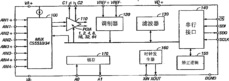
technical field [0001] The invention belongs to the technical field of signal processing, and relates to a signal conditioning circuit and a conditioning method thereof, in particular to a digital signal conditioning circuit and a conditioning method thereof based on a double-sampling structure chopper amplifier; in addition, the invention also relates to a double-sampling maintain the circuit. Background technique [0002] Chopper amplifiers are widely used in signal measurement systems due to their superior low offset characteristics. figure 1 Is a schematic diagram of the structure of a typical chopper amplifier. The input signal is modulated to the Chop frequency Fchop by the Chop switch SW1, and the offset voltage and the modulated input signal are amplified and then modulated by the Chop switch again, so that the input signal is modulated back to DC and the offset voltage is modulated to Fchop. After filtering out the offset voltage at Fchop, the amplified input si...

Claims


Application Information

Patent Timeline
Patent Type & Authority Patents(China)
IPC IPC(8): H03H17/02G11C27/02
Inventor 王照刚许刚
Owner 豪威国际控股有限公司
Learn More