
Light guide optical fiber andlight guide system thereof co-composing by coaxial semiconductor light source and light detector

A technology of coaxial light and semiconductor, applied in the field of coaxial light guide system, can solve the problems of unable to do high power output, irreplaceable, unfavorable power improvement, etc., and achieve the effect of avoiding the loss of incident light power

Active Publication Date: 2009-03-25
杨春足
View PDF6 Cites 5 Cited by
  • Summary
  • Abstract
  • Description
  • Claims
  • Application Information

AI Technical Summary

Problems solved by technology

The unstable current caused by this is not conducive to the increase of power, so that high-power output cannot be done, and it cannot replace the side-firing laser.
Therefore, the elliptical light output of side-fired lasers matching the circular core is still a shortcoming that does not conform to the laws of nature

Method used


Image

  • Light guide optical fiber andlight guide system thereof co-composing by coaxial semiconductor light source and light detector
  • Light guide optical fiber andlight guide system thereof co-composing by coaxial semiconductor light source and light detector
  • Light guide optical fiber andlight guide system thereof co-composing by coaxial semiconductor light source and light detector

Examples


Embodiment 1

[0114] Taking a coaxial optical fiber, a coaxial light source, and a coaxial photodetector to form an optical fiber with a coaxial coaxial structure and a transceiver end structure as an example, as shown in FIG. 15 for illustration. The components of the various reference numbers quoted in the examples of the present invention can be regarded as the same or functionally similar components, and it is intended to illustrate the main implementation features represented by the examples in a very simplified diagrammatic manner; therefore, this illustration It is not intended to depict all of the features of an actual embodiment, nor is it intended to depict the relative dimensions of the depicted components, so the figures shown are not drawn to scale, but are drawn in accordance with the general spirit of the coaxial light guide of the present invention.

[0115] Referring to Figure 15, the light source A is a coaxial semiconductor laser, which shows a partial cross-sectional view...

Embodiment 2

[0128] Figure 16 It is a simplified cross-sectional view of the structure of Embodiment 2 of the coaxial light guide system, which is an application example in which coaxial semiconductor transceivers are coaxially co-fabricated on the same substrate 1602 to share the only coaxial optical fiber 801 and save one optical fiber. In traditional fiber optic transceivers, the light source emitter and the light detector for optical signal reception are manufactured separately and then assembled together. Because the optical fiber itself has bidirectional optical waveguide capability, for example, the coaxial semiconductor optical transmitter and receiver of the present invention can be coaxially fabricated on the same substrate, which can save a lot of hardware construction costs. Because the three are coaxial, it is very easy to overlap up and down, co-construct and utilize each other, resulting in various application combinations. The upper layer of this transceiver is the APD phot...

Embodiment 3

[0130] Take a color display structure composed of 1024 coaxial color light emitting diodes in a horizontal row and 768 coaxial color light emitting diodes in a vertical row as embodiment 3, as shown in FIG. 17 for illustration. Referring to FIG. 17 , each light-emitting system in the color display is composed of 1024×768=786432 coaxial color light-emitting diodes as shown in FIG. 18 . Coaxial color light-emitting diodes are color light-emitting diodes (hereinafter referred to as coaxial color light-emitting diodes CCLED-COAXIAL COLOR LIGHT EMITTING DIODES) formed by sharing the axis of the coaxial three-color light-emitting diodes. 1801 is the three-color axis common electrode, 1802 is the red R layer, 1803 is the green G layer, 1804 is the blue B layer, 1805 is the red R coaxial outer ring power supply electrode, 1806 is the green G coaxial outer ring power supply electrode, 1807 is the blue B coaxial outer annular power supply electrode, 1808 is the base plate, 1809 is the t...


PUM

PropertyMeasurementUnit
Thicknessaaaaaaaaaa
Outer diameteraaaaaaaaaa

Abstract

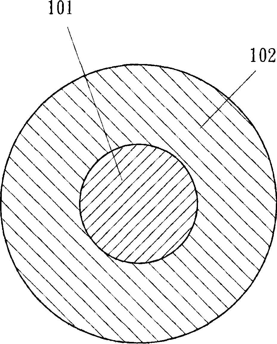
The invention relates to a coaxial light-guide optical fiber for a coaxial light-guide system, which is manufactured by distributing refractive indexes on the radius and is different from the prior optical fiber which is formed by distributing the refractive indexes on the diameter, wherein the refractive indexes of a circular shell and an axle center part which are coaxial with each other are the same; the center of refractive index distribution which is taken as the light-guide basis is shifted from an axle center to the radius of the optical fiber; and light is changed to be transmitted between the axle center and the circular shell which is coaxial with the axle center. Not only the novel orientation solves the problem that the refractive index distribution center of the prior optical fiber after manufacture is concave but also the luminous flux of the coaxial monomode fiber manufactured by the invention is larger than that of the prior monomode fiber, thereby increasing the communication distance. When the coaxial light-guide optical fiber is matched with an inner conductor and an outer conductor which are invented for coaxial power supply and are partitioned by a coaxial light source and a coaxial light tester which are formed by multilayered annular semiconductors, not only the problem of energy consumption when lateral emitting elliptical light sources are emitted into a circle core is solved but also the coaxial optical fiber, the coaxial light source and the coaxial light tester can be integrated into the perfectly photoelectrically matched coaxial light-guide system.

Description

technical field [0001] The invention relates to a coaxial light guide system co-constructed with an optical fiber used for communication, a light source and a light detector. Background technique [0002] Humans discovered glass 2,500 years ago, and it was not until the Roman era that glass was drawn into filaments for use. In the 1950s, the medical community used these bare-wire glass bundles to transmit images, hoping to make an endoscope; but the light leakage was too large to transmit the image clearly, because these bare-wire glasses had low purity and were made of air with a low external refractive index. Make a fully reflective layer. In 1956, Dr.Narinder Singh Kapany first coined the name "fiber optical" for the purpose of more accurately wrapping a layer of glass material with a lower refractive index on the bare glass filament as a shell, which can controllably cause total reflection and avoid The light leaks out to achieve a more complete optical fiber transmiss...

Claims


Application Information

Patent Timeline
IPC IPC(8): G02B6/10G02B6/42G02B6/00H04B10/12H04B10/135
Inventor 杨春足
Owner 杨春足
Learn More