
Non-contact oil layer thickness detecting method

A technology of oil layer thickness and detection method, which is applied in measurement devices, liquid/fluid solid measurement, liquid level indicator for physical variable measurement, etc.

Inactive Publication Date: 2009-03-25
SHANXI CHANGLI PETROLEUM TECH DEV CO LTD
View PDF0 Cites 11 Cited by
  • Summary
  • Abstract
  • Description
  • Claims
  • Application Information

AI Technical Summary

Problems solved by technology

However, the following two problems cannot be solved when these primary instruments "contacting" with materials are used in oil and gas field production links:
[0004] First, the crude oil produced by oil and gas field development generally contains different amounts of free water and emulsified water. The existence of the emulsified layer in the storage tank makes the oil / water interface blurred, which makes the existing oil-water interface detection on the market invalid and cannot pass Measure the relative level of the oil-water interface and the oil-gas interface (liquid level) to measure the thickness of the oil layer. For example, in the crude oil dehydration tank and the oily sewage treatment settlement deoiling tank, the "oil-water interface" is not obvious due to the existence of an emulsified layer between the oil layer and the water layer.
[0005] Second, impurities contained in crude oil or sewage, such as organic flocs, asphaltene, etc., will cause the primary detection instrument to "hang" and cause misreading of the measurement through the material characteristic "capacitance" or "resistance".
Therefore, even if there is a clear oil-water interface and is affected by the conductive material, the better the conductivity of the material, the greater the error will be; Liquid surface) moves, making "float" type sensing instruments such as reed switches, magnetic telescopic and other interface (or liquid level) instruments malfunction, and "hanging materials" will also cause misjudgment of optical fiber probes and misreading of liquid levels

Method used


Image

  • Non-contact oil layer thickness detecting method

Examples


Embodiment Construction

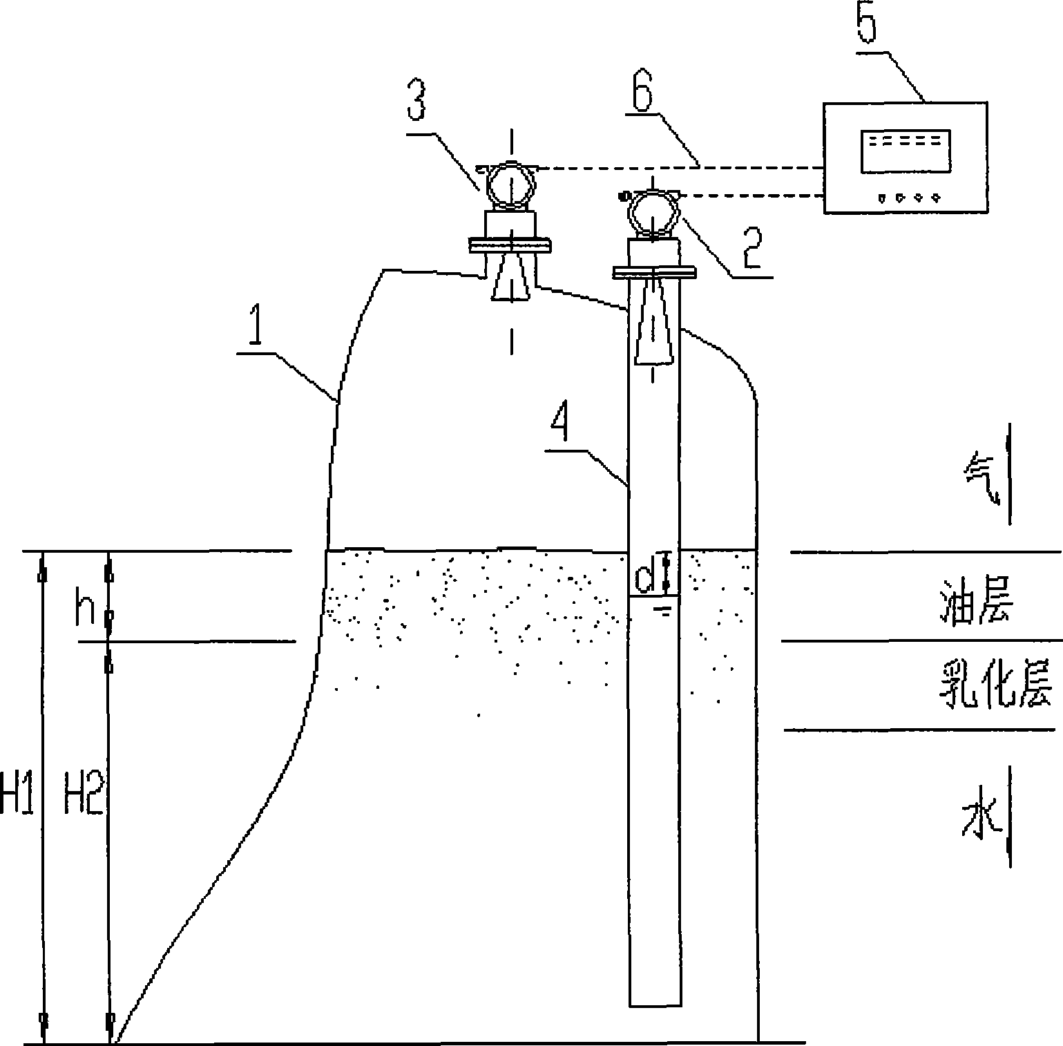
[0017] Such as figure 1 As shown, the interior of the water-containing oil tank 1 (which may be a lying tank or a pond) is respectively a gas phase space, an oil layer, an emulsified layer, and a water layer from top to bottom. The first liquid level detection instrument 2 and the second liquid level detection instrument 3 are respectively installed on the top of the tank (or pool top), and the second liquid level detection instrument 3 is at the top of the tank. The first liquid level detection instrument 2 is installed on the top of the oil layer isolation cylinder 4 . The first liquid level detection instrument 2 and the second liquid level detection instrument 3 are connected to the control box 5 (control unit) through the instrument cable 6, and the control box 5 provides power for the first liquid level detection instrument 2 and the second liquid level detection instrument 3 . After the control box 5 is powered on, the first liquid level detection instrument 2 measure...


PUM

PropertyMeasurementUnit
Diameteraaaaaaaaaa

Abstract

The invention belongs to a thickness detection method for a noncontact oil layer, which is characterized in that an oil layer isolating cylinder (4) is vertically fixed inside a water-containing oil tank (1) from the top down; a lower port of the oil layer isolating cylinder (4) is arranged on a water layer position of the water-containing oil tank (1); water of the water layer position naturally enters into the oil layer isolating cylinder (4); two sets of liquid-level detection devices are connected to the top of the water-containing oil tank (1) respectively; the liquid position of the water-containing oil tank (1) is detected from the top of the water- containing oil tank (1), and the liquid level in the oil layer isolating cylinder (4) is detected from the top of the oil layer isolating cylinder (4); a control unit is respectively connected with the two sets of liquid-level detection devices; and the thickness of the oil layer and the 'oil / water interface' level are calculated according to the difference value of two liquid levels on the inside and the outside of a tube body of the oil layer isolating cylinder (4) through further combination of the oil density value and the water density value, and are displayed on a control box (5). The thickness detection method for the noncontact oil layer can realize detection of the thickness of the oil layer of the water-containing oil tank and detection of the 'oil / water interface' level.

Description

technical field [0001] The invention belongs to the field of industrial measurement, especially a non-contact measurement of the oil layer thickness and the ideal "oil / water interface" level of crude oil dehydration settling tanks, settling oil removal tanks, sewage and oil pools, etc. involved in the production process of oil and gas fields. Oil layer thickness detection method. Background technique [0002] In the process of oil and gas field development, there are many process equipment and containers that need to determine the thickness of the oil layer, such as crude oil dehydration settling tanks, settling oil removal tanks, sewage sewage oil pools, etc.; especially the settlement oil removal tanks commonly used for oily sewage treatment, " The Code for Fire Protection of Petroleum and Natural Gas Engineering Design (GB50183-2004) stipulates that "the thickness of the oil accumulation on the top of the settling tank should not exceed 0.8m", but from the perspective of ...

Claims


Application Information

Patent Timeline
IPC IPC(8): G01B15/02G01B17/02G01F23/28G01F23/296
Inventor 李旭
Owner SHANXI CHANGLI PETROLEUM TECH DEV CO LTD
Learn More