
Dry vacuum pump

A dry vacuum pump, vortex technology, applied in the direction of rotary piston pump, pump, rotary piston machine, etc., to achieve the effect of small vibration, easy processing and small volume

Inactive Publication Date: 2010-12-29
NORTHEASTERN UNIV LIAONING +1
View PDF0 Cites 0 Cited by
  • Summary
  • Abstract
  • Description
  • Claims
  • Application Information

AI Technical Summary

Problems solved by technology

Roots type and Roots + claw combined structure make the gas path long and complicated, resulting in the accumulation of condensate and the possibility of being corroded by chemical gas greatly increased
Due to the multi-stage design, more seals are used between the stages, resulting in more parts and more leakage points, which makes the maintenance work more troublesome
Moreover, the Roots + claw dry pump has a large size and a large operating noise.
Screw and scroll vacuum pumps have special rotor shapes, which require high precision in processing, assembly, and positioning, and special machines must be used for processing, which has a high scrap rate, is not conducive to mass production, and has high costs. People have been looking for direct air exhaust. dry vacuum pump

Method used


Image

  • Dry vacuum pump
  • Dry vacuum pump
  • Dry vacuum pump

Examples


Embodiment Construction

[0013] The present invention is further described in conjunction with accompanying drawing:

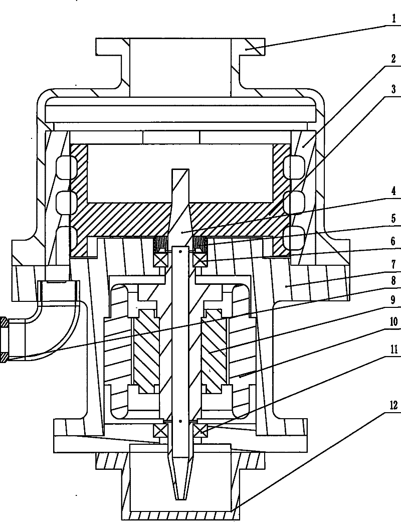
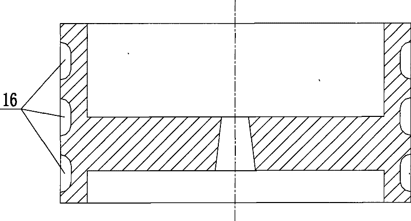
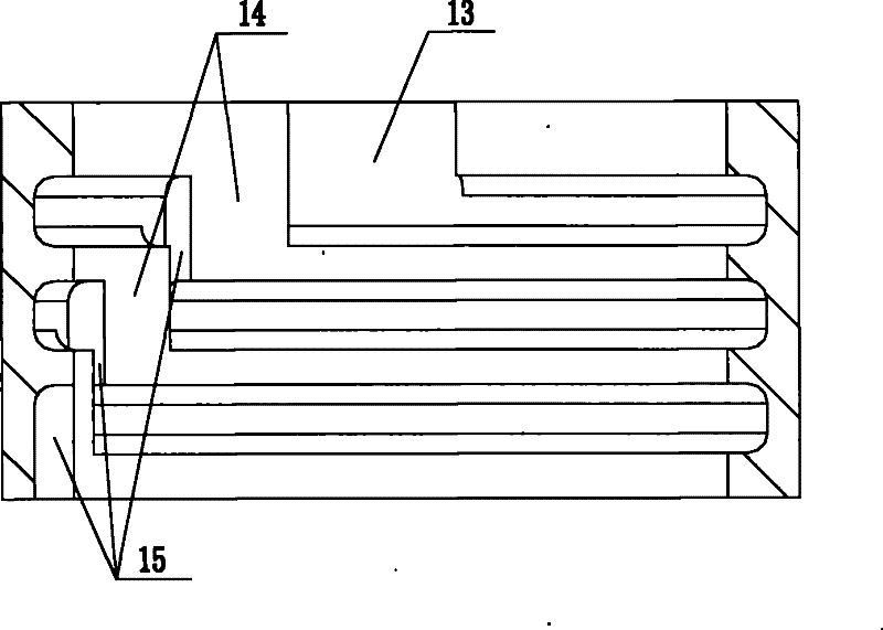
[0014] like figure 1 It is a structural schematic diagram of an embodiment of the present invention, including a base 7, a motor rotor 9 connected to the base 7, a rotor 3 connected to the main shaft 4, and an oil suction hole is provided in the center of the main shaft 4, and the oil suction hole leads into the lubricating oil pool at the bottom of the base In 12, the main shaft 4 is provided with an oil outlet, and the oil outlet is composed of a plurality of oil outlet holes, and the oil outlet holes are located near the upper bearing 6 and the lower bearing 11, providing lubricating oil for the upper bearing 6 and the lower bearing 11, and the upper bearing 6 and the lower bearing 11 adopt rolling bearings, and the seal adopts mechanical seal 5; the rotor 3 is composed of three-stage vortex-stage rotors, and the outer side of each vortex-stage rotor is provided with an annular gr...


PUM


Abstract

The invention discloses a dry vacuum pump, which relates to the vacuum technology. The dry vacuum pump comprises a base, a motor, a rotor and a stator, wherein the rotor consists of at least one level of vortex level, and the outer side of each level of vortex level is circumferentially provided with an annular groove in which blades of same height as the groove are uniformly distributed; the inner circumference of the stator is provided with vortex grooves the level number of which is the same as the level number of vortex level of the rotor; a section of a risen convex plate is arranged in the vortex groove, and each level of vortex groove and the corresponding one level of vortex level form a level extraction compressing unit; and an exhaust duct is arranged between the adjacent extraction compressing units and is positioned between the adjacent vortex grooves of the inner circumference of the stator. The dry vacuum pump is capable of discharging into atmosphere directly, and has the advantages of simple structure, few parts, easy processing and simple maintenance; meanwhile, moving pieces in the pump have no friction to a pump cavity, so the pump has almost no wear, little vibration and low noise.

Description

technical field [0001] The invention relates to the field of vacuum technology, in particular to a dry vacuum pump. [0002] Background technique [0003] In recent years, people have developed various types of dry pumps, which are widely used in various fields of vacuum applications such as semiconductor industry, analytical instruments and electronics industry. Existing dry pumps can be roughly divided into dry vacuum pumps according to different mechanical structures: Roots type, Roots+claw type, screw type, scroll type, etc. Roots type and Roots + claw combined structure make the gas path long and complicated, resulting in the accumulation of condensate and the possibility of being corroded by chemical gas greatly increased. Because they are all multi-stage designs, and seals are often used between stages, there are more parts and leakage points, which makes maintenance more troublesome. Moreover, the Roots+claw type dry pump has a large external dimension and relative...

Claims


Application Information

Patent Timeline
Patent Type & Authority Patents(China)
IPC IPC(8): F04C25/02F04C18/02
Inventor 刘坤肖玉常学森巴德纯
Owner NORTHEASTERN UNIV LIAONING
Learn More