
Graphite-filled vacuum glass tube open type capillary pipe solar thermal-collecting tube

A solar collector tube and vacuum glass tube technology, which is applied in the field of solar collectors, can solve the problems of difficulty in meeting the pressure bearing requirements of a building heating system, affecting the efficiency of solar energy transfer, and low temperature of hot water outlet, etc., so as to eliminate air thermal resistance. , Small pipe diameter, the effect of improving the pressure bearing capacity

Inactive Publication Date: 2009-03-18
DALIAN UNIV OF TECH
View PDF0 Cites 4 Cited by
  • Summary
  • Abstract
  • Description
  • Claims
  • Application Information

AI Technical Summary

Problems solved by technology

For this type of U-tube vacuum glass tube collector, due to the consideration of installation and thermal expansion requirements, there is a large contact thermal resistance between the aluminum wing sheath and the glass tube, and between the U-shaped tube and the fins, which affects the Transfer efficiency of solar energy from outside to inside, to working medium in U-shaped tube
For ordinary vacuum glass tube collectors without U-shaped tubes, there are problems that the tubes use water as the medium, and the glass tubes are easy to freeze and crack in winter. Thermal system pressure requirements and other issues

Method used


Image

  • Graphite-filled vacuum glass tube open type capillary pipe solar thermal-collecting tube
  • Graphite-filled vacuum glass tube open type capillary pipe solar thermal-collecting tube
  • Graphite-filled vacuum glass tube open type capillary pipe solar thermal-collecting tube

Examples


Embodiment Construction

[0017] The specific embodiments of the present invention will be described in detail below in conjunction with the technical solution and the drawings.

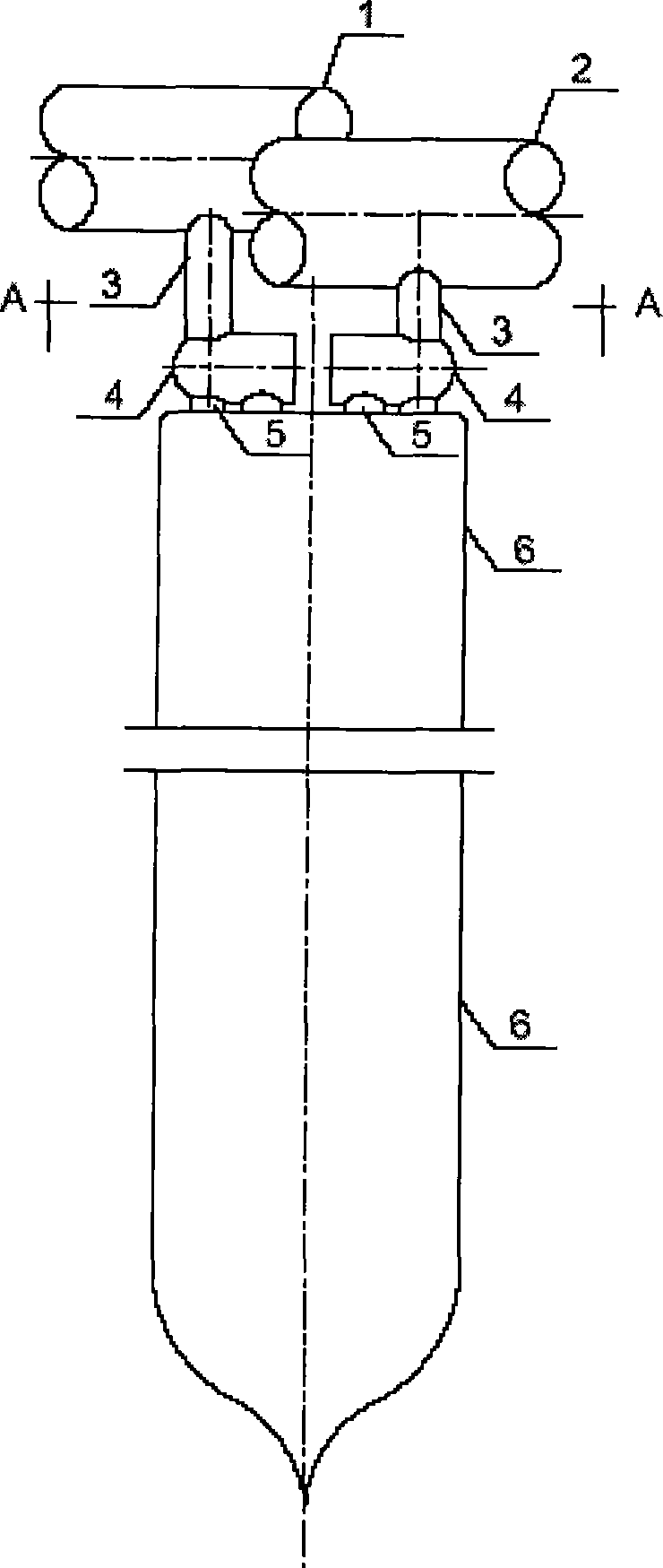
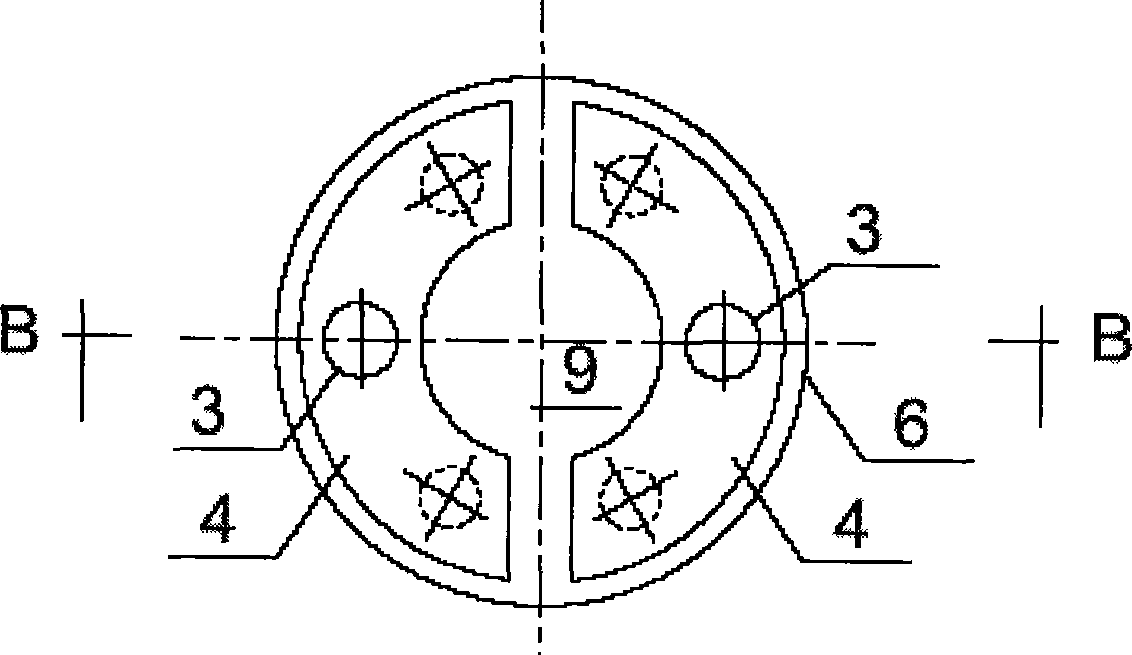
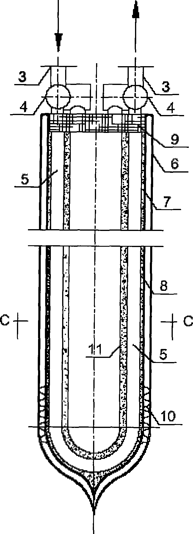
[0018] The graphite-filled vacuum glass tube open capillary solar heat collector tube of the present invention is mainly composed of a first header tube 1, a second header tube 2, a header connection tube 3, a manifold 4, a U-shaped capillary metal tube 5, and an outer glass tube 6. , Inner glass tube 7, graphite packing 8, heat insulation seal head 9 and elastic support 10; the first header tube 1 and the second header tube 2, the header connection 3, the manifold 4 and the U-shaped capillary metal tube 5 The successive connection between them adopts welding connection; the U-shaped capillary metal tube 5 is installed in the graphite packing 8 to form a whole and installed in the vacuum glass tube, and the upper opening of the vacuum glass tube is sealed with an adiabatic sealing head 9; the inner glass After the outer surface o...


PUM


Abstract

The invention discloses a graphite filled vacuum glass tube open type capillary solar heat collection tube, which belongs to the field of solar heat collector. The solar heat collection tube is characterized in that the device comprises a header tube, a header connecting tube, liquid distribution and collection tubes, capillary metal tubes, an external glass tube, an internal glass tube, graphite packing, a thermal insulated seal head, and an elastic support; the graphite packing is compactly packed among the internal glass tube, the capillary metal tubes and the thermal insulated liner tube to reinforce the heat transfer performance; the inner diameter of each capillary metal tube is between 2 and 5 millimeters, and the capillary metal tubes are connected with the liquid distribution and collection tubes; and water, Freon or other heat transfer media enter the U-shaped capillary metal tubes through the header tube, the header connecting tube and the liquid distribution tube, are heated after absorbing solar energy of the vacuum glass tubes, and then enter the header tube through the liquid collection tube and are discharged so as to complete the process of solar heat collection, working media heating and heat conveying. The graphite filled vacuum glass tube open type capillary solar heat collection tube has the advantages that a plurality of capillary tubes increase the heat exchange area of the working media and improve the heat transfer performance of the heat collection tube; and simultaneously the heat supply temperature of the heat collection tube is increased.

Description

Technical field [0001] The invention belongs to the field of solar heat collectors, and relates to using a plurality of U-shaped metal capillary tubes to realize a solar heat collection element with high pressure bearing capacity, high heat collection efficiency and good heat exchange performance. Background technique [0002] The solar collector is the key equipment of various solar energy utilization systems, and the solar collector tube is the core of the solar collector. At present, there are two types of solar collectors: flat plate collectors and evacuated tube collectors. The latter is the most widely used and most likely to realize high-temperature collectors in China. The existing vacuum glass tube collector uses a single U-shaped tube, and the U-shaped tube is installed on an aluminum wing sheath with fins. For this type of U-tube evacuated glass tube collector, due to consideration of installation and thermal expansion requirements, there are large contact thermal resi...

Claims


Application Information

Patent Timeline
Patent Type & Authority Applications(China)
IPC IPC(8): F24J2/05F24J2/24F24J2/46F24J2/48F24S10/40F24S10/70
CPCY02E10/44F24S10/45F24S10/75
Inventor 张吉礼马良栋
Owner DALIAN UNIV OF TECH
Learn More