
LED light source assembly

An LED light source and LED chip technology, applied in the field of lighting, can solve the problems of high heat dissipation cost, difficult to blow in the wind, inconvenient LED light source, etc., and achieve the effect of realizing heat dissipation effect, reducing cost and solving the phenomenon of light decay.

Inactive Publication Date: 2009-03-18
金明武
View PDF0 Cites 7 Cited by
  • Summary
  • Abstract
  • Description
  • Claims
  • Application Information

AI Technical Summary

Problems solved by technology

The heat dissipation cost of heat sinks or heat pipes is high, and if fans are used for heat dissipation, because the substrate of the LED light source and the light-transmitting tube are too close, it is difficult for the wind to blow in, causing the temperature of the LED light source to not drop.
[0006] In summary, it can be seen that the LED light source of the prior art obviously has inconvenience and defects in actual use, so it is necessary to improve it.

Method used


Image

  • LED light source assembly
  • LED light source assembly
  • LED light source assembly

Examples


Embodiment Construction

[0035] In order to make the object, technical solution and advantages of the present invention clearer, the present invention will be further described in detail below in conjunction with the accompanying drawings and embodiments. It should be understood that the specific embodiments described here are only used to explain the present invention, not to limit the present invention.

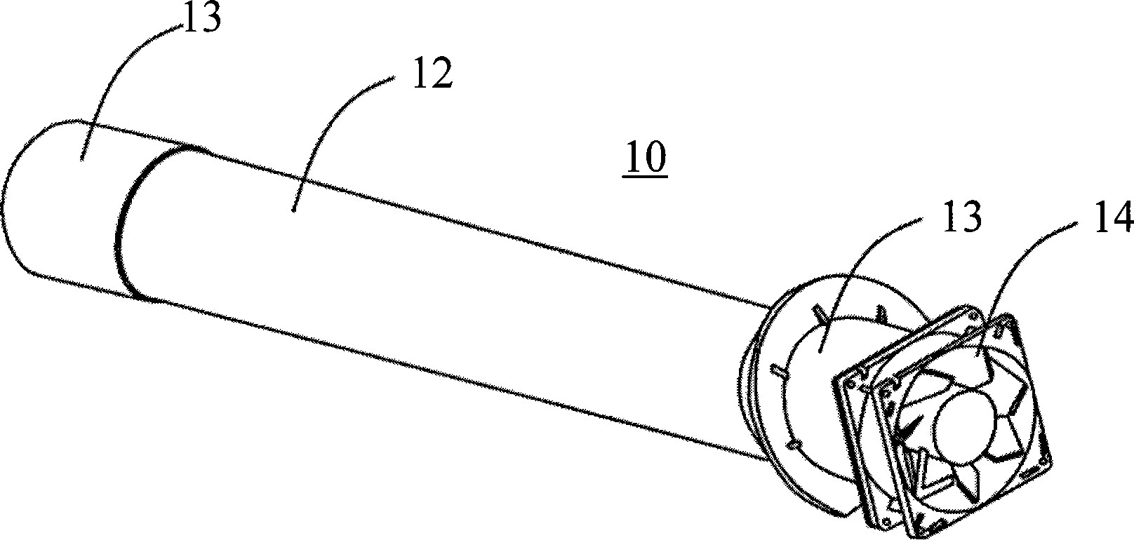
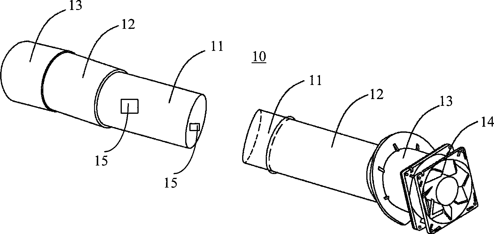
[0036] The basic idea of ​​the present invention is to change the traditional flat LED light source into a cylindrical LED light source, and the cylindrical LED light source can be directly installed in the traditional lamp housing, thereby facilitating the popularization and popularization of the application of the LED light source.

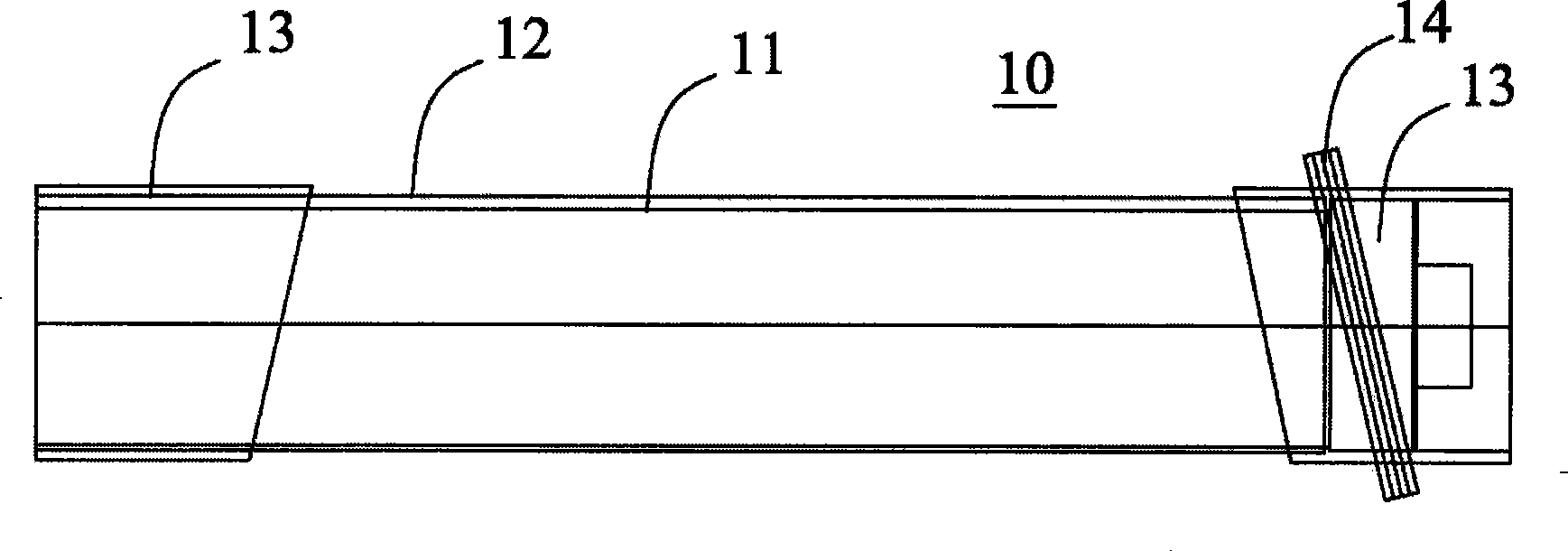
[0037] Figure 1 ~ Figure 3 The structure of the preferred LED light source assembly of the present invention is shown. The LED light source assembly 10 includes a cylindrical LED light source 11, a light-transmitting tube body 12 and two joints 13, and the two joint...


PUM


Abstract

The invention discloses an LED light source component which comprises an LED light source and joints respectively sleeved on two ends of the LED light source. The LED light source is a cylindrical surface type LED light source which comprises at least one cylindrical surface type baseplate; and the cylindrical surface type baseplate is in electric connection with a plurality of LED chips. Therefore, the cylindrical surface type LED light source can be directly arranged inside the prior lamp shell through the joints and can be directly exchanged with the prior light source, thereby greatly reducing the cost for reconstructing the prior light source to the LED light source and being favorable for popularization and application of the LED light source. In addition, a photosensor is arranged near the cylindrical surface type baseplate of the LED light source; and the photosensor is used to sense the attenuation of a light intensity signal of the LED light source and control the size of output power of the LED light source so as to solve the phenomenon of light attenuation of the prior LED light source.

Description

technical field [0001] The invention relates to the technical field of lighting, in particular to an LED light source assembly. Background technique [0002] With the continuous development of science and technology, light source products are constantly being introduced: from incandescent lamps to mercury lamps, to metal halide lamps, to sodium lamps (high pressure, low voltage), until now LED (Light Emitting Diode, light emitting diode) semiconductor lamps . LED semiconductor lamps are more and more favored by people because of their long life, energy saving, environmental protection and other advantages. [0003] LED semiconductor lamps are generally composed of LED light sources, heat sinks, reflectors, and lamp housings. Existing LED semiconductor lamps use a flat panel lighting arrangement, and the LED light source is a flat LED light source, that is, several LED chips are welded on a flat substrate, such as a flat PCB (Printed Circuit Board, printed circuit board). ...

Claims


Application Information

Patent Timeline
Patent Type & Authority Applications(China)
IPC IPC(8): F21V19/00F21V5/00F21V29/02H01L23/34F21Y101/02F21V29/51F21V29/89F21Y115/10
CPCH01L2924/0002
Inventor 金明武张道静
Owner 金明武
Learn More