Dental handpiece

A dental and handpiece technology, applied in the field of dental handpieces, which can solve problems such as powder exhaustion

Inactive Publication Date: 2009-03-18
NAKANISHI INC
View PDF2 Cites 6 Cited by
  • Summary
  • Abstract
  • Description
  • Claims
  • Application Information

AI Technical Summary

Problems solved by technology

Due to the tendency of such a flow rate change, there is an advantage that it is easy to confirm the cleaning effect at the initial stage of cleaning the surface of the teeth, but there is a problem that the powder filled in the container will be used up in a short time.

Method used


Image

  • Dental handpiece
  • Dental handpiece
  • Dental handpiece

Examples


Embodiment 1

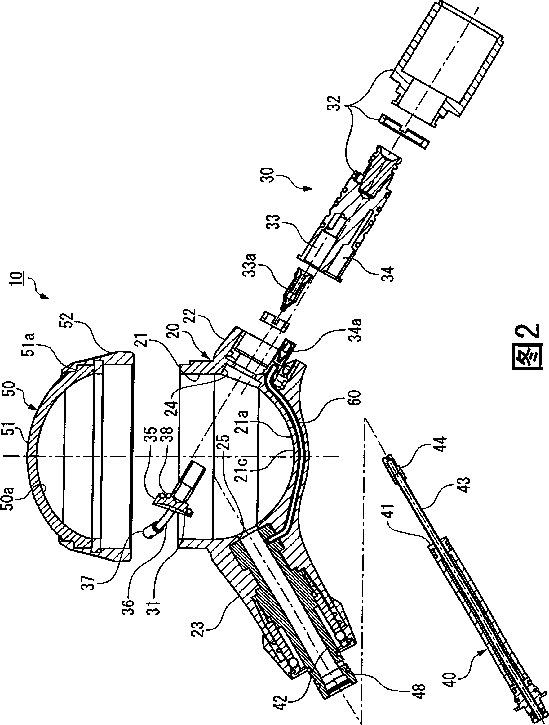
[0071] In the head 10 as described above, the diameter of the space S is 36 mm, the blowing holes 37 a, 37 b, and 37 c of the nozzle 37 are each φ0.5 mm, and the blowing hole 37 b is toward the center C of the space S with respect to the vertical downward direction. For example, it is inclined at 60°, and the blowing hole 37 c is formed at an inclination of, for example, 30° toward the inner peripheral surface 21 a side of the concave portion 21 relative to the vertical downward. Then, 15 g of calcium carbonate was accommodated in the concave portion 21 as powder, and compressed air at a pressure of 0.3 MPa was fed.

[0072] Then, the relationship between the elapsed time and the cumulative cutting area was obtained from the remaining amount of powder per minute.

Embodiment 2

[0074] Also, for comparison, as Figure 5 As shown, the blowing hole 37a formed on the front end of the nozzle 37 is φ0.4mm, and three blowing holes 37b, 37c, 37d of φ0.4mm are formed on the outer peripheral surface at angles of 60° each. Using this nozzle 37, the relationship between the elapsed time and the cumulative cut area was obtained in the same manner as above.

Embodiment 3

[0076] No blowout hole was formed at the tip of the nozzle 37, and only two blowout holes of φ0.5 mm were formed on the outer peripheral surface. One of the blowing holes formed on the outer peripheral surface blows out air obliquely, and the air flows along the inner peripheral surface 21 a of the concave portion 21 from the side where the nozzle 37 is provided to the opposite side. Using this nozzle 37, the relationship between the elapsed time and the cumulative cut area was obtained in the same manner as above.


PUM


Abstract

The invention provides a dental handpiece which realizes stabilization of power in projecting flow, increases durability of the power, meanwhile increases cutting efficiency. Two nozzles (37) in pair are provided along an inner circumferential surface (21a) of a concavity (21), air is blown out in a space from a blowout hole (37a) provided at a tip end portion of the nozzle from a side where the nozzle (37) is provided aiming at an opposite side along an inner circumferential surface of the space and a powder contained in the concavity (21) is caused to rise up in the space, whereby the condition of the powder mixed with the air within the space is improved. Furthermore, under the condition that the power housed in the concavity is excessive, through the blowout hole formed on the side ofthe nozzle to blow out the air, the power accumulated near the surface of the power in the concavity is blown out. Under the condition that the power housed in the concavity is little, through the blowout hole formed on the side of the nozzle to blow out the air, the power is blown out from a bottom (21c) of the concavity.

Description

technical field [0001] The present invention relates to dental handpieces for dental treatment by blowing a mixture of powder and air together with water onto teeth. Background technique [0002] Dental handpieces are known that mix powder for grinding or cleaning teeth with air, and spray the mixture of powder and air onto the surface of the teeth together with water. [0003] Such a dental handpiece includes, for example, a container for storing powder, an air supply path for supplying air into the container, a mixture transfer path for transferring a mixture of powder and air to the discharge nozzle, and A water transfer path for transferring water to be sprayed onto the tooth surface together with the mixture to the ejection nozzle, and further, a tube for communicating with the air supply path and the mixture transfer path is protruded from the inside of the container. Holes are pierced at the front ends of the protruding pipes to serve as air blowing holes and mixture...

Claims


Application Information

Patent Timeline
Patent Type & Authority Applications(China)
IPC IPC(8): A61M11/02A61C19/06
CPCA61C3/025A61C1/08A61C1/10
Inventor 高森昭一张替勇介
Owner NAKANISHI INC
Why Eureka
Try Eureka