
PLL filter

A filter and low-pass filter technology, applied in the direction of automatic power control, impedance network, electrical components, etc., can solve the problems of nonlinear distortion of the output signal, relatively high linearity requirements, error vector amplitude and other problems, to reduce the chip Power consumption, avoid nonlinear distortion, save chip area effect

Active Publication Date: 2011-02-23
RDA TECH
View PDF5 Cites 0 Cited by
  • Summary
  • Abstract
  • Description
  • Claims
  • Application Information

AI Technical Summary

Problems solved by technology

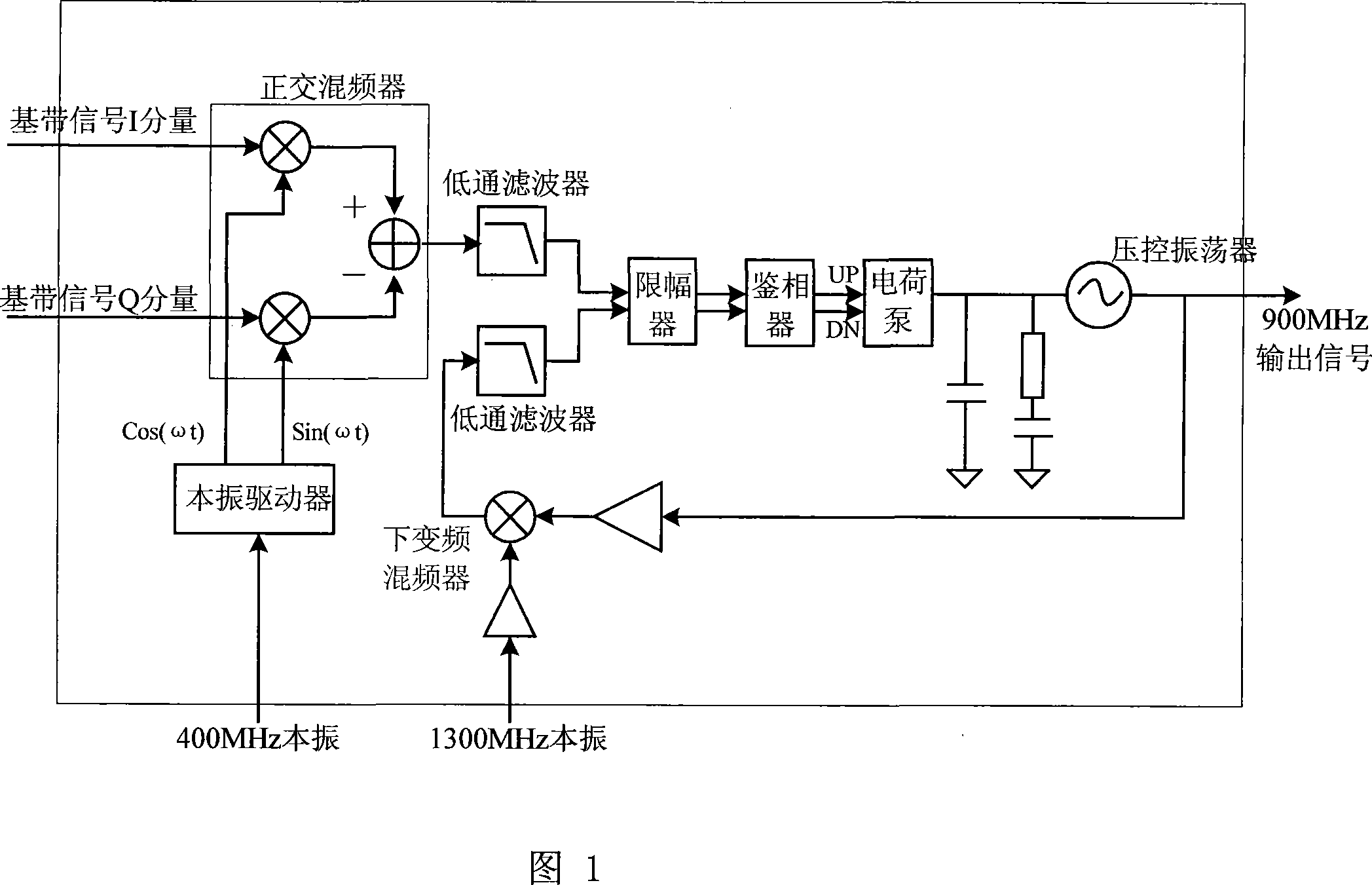
[0004] The above offset pll filter has the following disadvantages, it needs to provide 2 LO signals, so it is necessary to integrate 2 PLLs in the system to generate LO signals; the IF intermediate frequency needs to be mixed Filtering the post-frequency signal requires two low-pass filters working at the IF intermediate frequency. The linearity requirement of the IF intermediate frequency filter is relatively high. If the linearity cannot meet the index, it will bring nonlinear distortion to the final output signal. Affects EVM (error vector magnitude); due to the presence of two LO signals in the pll loop at the same time, if the circuit and layout design are unreasonable, the cross-coupled feedthrough of the clock will bring unwanted spur emission spurs in the output spectrum

Method used


Image

  • PLL filter
  • PLL filter
  • PLL filter

Examples


Embodiment Construction

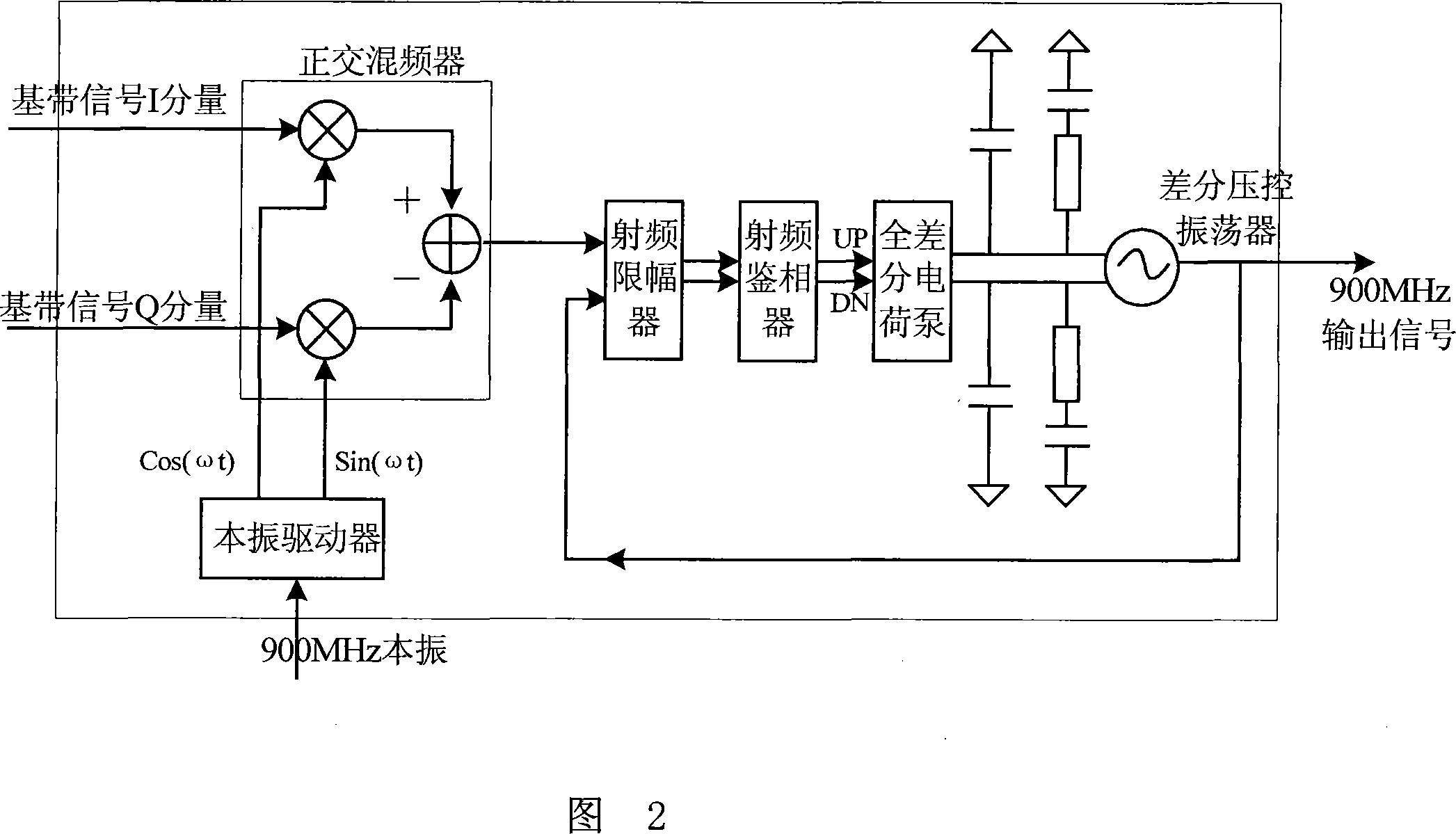
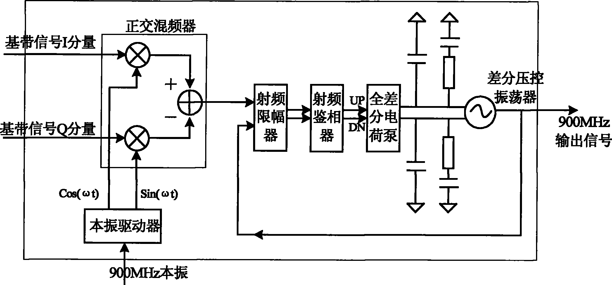
[0013] A specific embodiment of the PLL filter of the present invention is as figure 2 As shown, only one radio frequency local oscillator signal (RF LO) needs to be provided from the outside. The frequency of this signal is the same as the final desired RF output frequency, which is selected around 900MHz. The local oscillator signal enters the local oscillator driver module of the PLL filter to improve its Drive capability, and perform phase shift operation at the same time to generate two orthogonal RF local oscillator signals, and then through the quadrature mixer, the I and Q components of the baseband signal provided by the external analog baseband chip are up-converted, and modulated to the RF carrier Frequency modulation signal, the modulation signal is directly used as an input of the radio frequency limiter, and the other input of the radio frequency limiter is directly fed back from the 900MHz radio frequency signal output by the differential voltage controlled osci...


PUM


Abstract

The invention discloses a PLL filter. A radio frequency intrinsic signal the frequency of which is the same as the frequency of a final radio frequency output signal is connected with an intrinsic drive module in an external connection way to generate two paths of quadrature radio frequency intrinsic signals, then a baseband signal I and Q components connected in the external connection way are performed with frequency up-conversion by a quadrature mixer, a modulation signal modulated to the radio frequency carrier frequency is obtained and directly used as the input of a radio frequency limiter, the other input of the radio frequency limiter is a feedback signal of the final radio frequency output signal, the two paths of input signals are limited by the radio frequency limiter, then thephases of the two paths of input signals are compared according to the frequency of the radio frequency by a radio frequency phase detector, an upper charge signal or a lower discharge signal is generated to control the output of a fully differential charge pump, fully differential control voltage is output to control the oscillation frequency of a differential voltage controlled oscillator via afully differential low-pass filter, and the final radio frequency output signal is output. The PLL filter has the advantages of small nonlinear distortion and little stray emission in the output frequency spectrum.

Description

technical field [0001] The invention relates to an electronic circuit, in particular to a radio frequency PLL filter. Background technique [0002] With a large number of applications of wireless communication systems, wireless communication signals of various frequencies and applications exist in the space at the same time. In order to ensure that each communication system will not interfere with each other, all communication standards have strict restrictions on the signal spectrum emitted by the communication system. For a wireless transmission system, the far-end noise power of the transmitted signal is a harsh indicator. Taking the GSM system as an example, the standard stipulates that the noise energy at a position 20MHZ away from the transmitted signal should be lower than -162dBc / Hz in the transmission spectrum, but for ordinary up-modulation mixers, the noise floor at 20MHZ is already as high as -140~ -150dBc / Hz, it will not be possible to meet the system requirem...

Claims


Application Information

Patent Timeline
Patent Type & Authority Patents(China)
IPC IPC(8): H03L7/089H03H7/06H04B1/04
Inventor 叶晓斌魏述然
Owner RDA TECH
Learn More