LED illuminating apparatus and regulation method for using illumination homogeneity thereof

A technology of LED lighting and uniformity, applied in the field of lighting, can solve the problems that projectors or scientific instruments cannot be directly used, and the brightness of a single LED is low, so as to achieve the effect of improving uniformity and wide application range

Inactive Publication Date: 2009-03-11
GUANGDONG VTRON TECH CO LTD
View PDF0 Cites 5 Cited by
  • Summary
  • Abstract
  • Description
  • Claims
  • Application Information

AI Technical Summary

Problems solved by technology

[0003] However, at present, the brightness of a single LED is still relatively low, and high-power LEDs can only achieve tens of lumens, which cannot be compared with commonly used high-pressure mercury bulbs, which have hundreds to thousands of lumens.
Therefore, the combination design of various application LEDs came into being, but mainly focused on commonly used street lighting, traffic signal lights and household lighting (bulbs or lamp tubes), the distribution or shape of the light energy spot is determined by its specific use. designed and cannot be used directly in projectors or scientific instruments

Method used


Image

  • LED illuminating apparatus and regulation method for using illumination homogeneity thereof
  • LED illuminating apparatus and regulation method for using illumination homogeneity thereof
  • LED illuminating apparatus and regulation method for using illumination homogeneity thereof

Examples


Embodiment 1

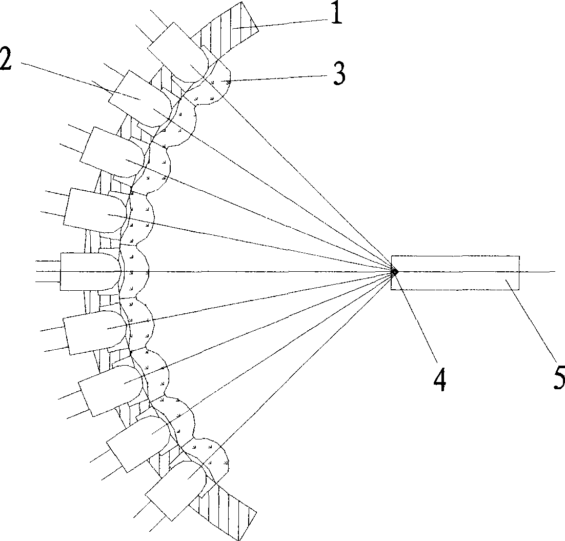
[0026] An LED lighting device such as figure 1 Shown, comprise a plurality of LED2, spherical support surface 1, condenser lens 3, a plurality of LED2 points to spherical surface center 4 and is fixedly installed on the spherical support surface 1, LED2 front is provided with condenser lens 3 and light pipe 5 successively according to light path order; The optical lens 3 is a plurality of independent small lenses corresponding to the LED2 one by one, located in front of the LED2, focusing the light emitted by the LED2 on the center of the spherical support surface 1, and the condenser lens 3 can be attached to the spherical support surface 1 The inner surface of the spherical support surface 1 may also have a certain distance, as long as the condenser lens 3 can focus the light beam emitted by the LED2 on the center of the spherical support surface 1 .

[0027] Each beam of light emitted by the LED 2 converges to the spherical center 4 after passing through the corresponding l...

Embodiment 2

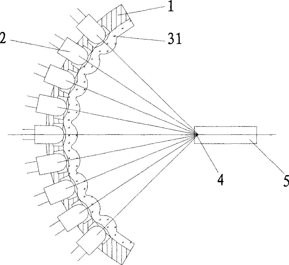
[0029] An LED lighting device such as figure 2 As shown, the difference from Embodiment 1 is that the condensing lens 31 is a lens array composed of a plurality of small lenses corresponding to the LED2, and the lens array is an integral structure.

Embodiment 3

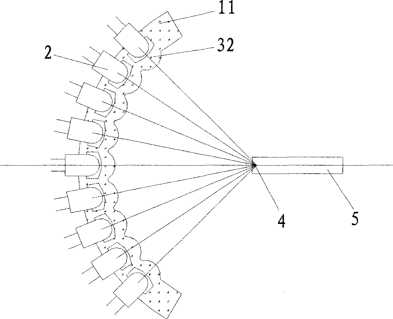
[0031] An LED lighting device such as image 3 As shown, the difference from Embodiment 2 is that the spherical support surface 11 and the condenser lens 32 are an integral structure, and the entire structure is made of transparent optical material by direct pressing with a mold, which can reduce the manufacturing cost.


PUM


Abstract

The invention provides an LED illumination device, comprising a plurality of LEDs, a spherical bearing surface and a condensing lens; a plurality of LEDs are fixedly arranged on the spherical bearing surface and point at the spherical center of the spherical bearing surface; the condensing lens is arranged before the LEDs; furthermore, a plurality of LEDs, the condensing lens and subsequent optical systems are sequentially connected by optical paths. The invention also provides an adjusting method used for illumination uniformity of the LED illumination device; optical energy emitted by all LEDs are changed by adjusting the input power of all LEDs, thus adjusting the uniformity of output illuminance of the illumination device further. The LED illumination device and the adjusting method have the advantages of high brightness and simple illuminance adjustment, can replace mercuric bulbs to be directly applied to illumination of projectors or other instruments, and have wide usage range.

Description

technical field [0001] The invention relates to the technical field of lighting, in particular to an LED lighting device and a method for adjusting lighting uniformity thereof. Background technique [0002] In recent years, with the rapid development of high-power and high-brightness LED technology, LED, as a new type of long-life environmental protection light source, has been more and more widely used in the field of lighting. Compared with commonly used high-pressure mercury bulbs, LED light sources have low operating voltage, low power consumption, extremely short luminous response time, pure light color, firm structure, impact resistance, vibration resistance, stable and reliable performance, light weight, small size, Low cost and other advantages, its development is advancing by leaps and bounds. The color purity of the LED light source is extremely high, which can improve the color rendering performance of the instrument. In the field of image display, the color gamu...

Claims


Application Information

Patent Timeline
IPC IPC(8): F21V19/00F21V21/00F21V5/04F21Y101/02F21Y107/10F21Y115/10
Inventor 孟凡华骆健忠
Owner GUANGDONG VTRON TECH CO LTD
Why Eureka
Try Eureka