
Light source device

A technology of a light source device and a light-emitting part, which is applied to light sources, point light sources, lighting devices, etc., can solve the problems of temperature rise of luminous tubes, shortening of lamp life, and decrease of light quantity, and achieve the effect of maintaining lamp life and suppressing the decline of light quantity

Inactive Publication Date: 2012-05-23
USHIO DENKI KK
View PDF1 Cites 0 Cited by
  • Summary
  • Abstract
  • Description
  • Claims
  • Application Information

AI Technical Summary

Problems solved by technology

[0009] However, if sealing is performed without cooling air flowing in, the gas containing siloxane stays in the airtight space inside the reflector 3, so when siloxane adheres to the surfaces of the discharge lamp 1 and the reflector 3, white spots are generated. , resulting in the problem that the amount of light drops
In addition, when siloxane adheres to the arc tube of the discharge lamp, the temperature of the arc tube rises, which causes the problem of shortening the life of the lamp.

Method used


Image

  • Light source device
  • Light source device
  • Light source device

Examples


Embodiment Construction

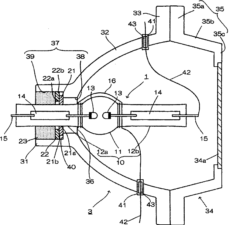
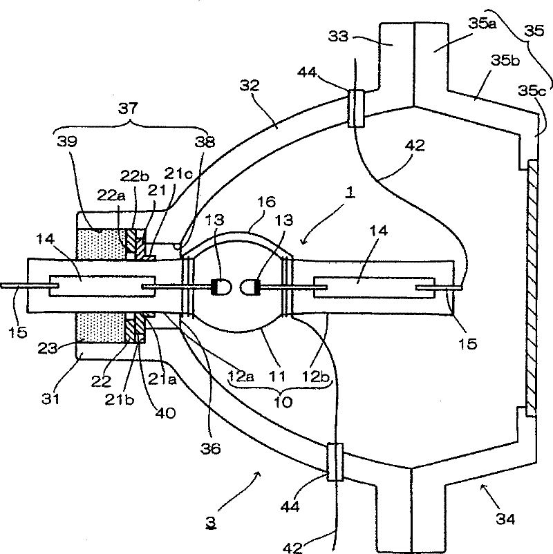
[0020] A first embodiment of the present invention will be described with reference to the drawings. figure 1 It is a cross-sectional view showing a light source device according to an embodiment of the present invention. The light source device is composed of a discharge lamp 1 and a reflector 3 surrounding the discharge lamp 1, and is configured so that the optical axis of the reflector 3 is substantially consistent with the arc direction of the discharge lamp 1, and the arc bright point of the discharge lamp 1 is aligned with the first arc of the reflector 3. One focus.

[0021] The reflecting mirror 3 is made of metal or heat-resistant glass, and is generally a bowl-shaped elliptical converging mirror composed of a head 31 and a reflecting part 32 . A dielectric multilayer film is formed on the surface of the reflector 32 facing the discharge lamp 1 to serve as a reflective surface. A front glass 34 composed of a base 35 and a window 34 a is provided in close contact wi...


PUM


Abstract

The invention provides a light source device, which can prevent surfaces of an electric discharge lamp and a reflecting mirror from producing white spots caused by siloxane, inhibit light quantity decline, and maintain service life of the lamp. The light source device is provided with the electric discharge lamp and the reflecting mirror, wherein a pair of electrodes is arranged in an illuminating part, and sealing parts are formed at two ends of the illuminating part; the reflecting mirror comprises a reflecting part and a head projecting from a central bottom, the interior of the head is provided with a narrow part beginning from the reflecting part and a communicating hole formed by a concave part connected with the narrow part, one sealing part of the electric discharge lamp is inserted into the communicating hole and fixed by adhesive filled at the concave part, a lateral surface connecting the narrow part and the concave part forms an abutting surface vertical to a tubular axle of the electric discharge lamp, and the lateral surface comprises a first gasket inserted into the sealing part and abutted with the abutting surface and a second gasket inserted into the sealing partand abutted with the first gasket, wherein the inside diameter of the first gasket is the outside diameter of the sealing part, the outside diameter is smaller than the diameter of the concave part, the inside diameter of the second gasket is larger than the outside diameter of the sealing part, and the outside diameter is diameter of the concave part.

Description

technical field [0001] The present invention relates to a light source device used as a light source for a liquid crystal display device, a projection projector device, and the like. Background technique [0002] Currently, in liquid crystal display devices, projection projector devices, and the like, light source devices configured by combining, for example, a light source made of a discharge lamp and a reflector are used. [0003] Figure 4 It is a schematic explanatory diagram showing the configuration of an example of a conventional light source device using a discharge lamp. [0004] Like the invention described in Japanese Patent Application Laid-Open No. 2002-62586, in this light source device, the discharge lamp 1 is assembled into the reflector 3, and the optical axis of the discharge lamp 1 coincides with the central axis of the reflector 3. A head 31 is provided on a central bottom 36 of the reflection mirror 3 , and a narrow portion 38 is formed on the reflectio...

Claims


Application Information

Patent Timeline
Patent Type & Authority Patents(China)
IPC IPC(8): F21V15/06F21V19/00F21V7/00H01J61/00F21V29/15F21Y101/00
Inventor 岩林弘久
Owner USHIO DENKI KK
Learn More