
Laser surface micro forming device and method

A surface micromodeling and laser technology, which is applied in laser welding equipment, optics, optical components, etc., can solve problems such as difficult processing, poor stability and reliability, and limited amount of material removal, so as to reduce wear and prolong service life. Effect

Inactive Publication Date: 2009-03-11
JIANGSU UNIV
View PDF2 Cites 34 Cited by
  • Summary
  • Abstract
  • Description
  • Claims
  • Application Information

AI Technical Summary

Problems solved by technology

However, the copper evaporation laser has a large size, high price, poor reliability, and heavy maintenance workload, so it is not suitable for large-scale industrial production.
③A patent application with application number 200310111573.3 discloses a manufacturing method and device for excimer laser electrochemical microstructures, which can process micron-scale microstructures on substrates such as semiconductors and metals, but this method has high operating costs , Insufficient stability, difficult to process ceramic materials and other shortcomings
④A patent application with application number 03116837.x discloses a method for processing periodic microstructures on metal thin films using femtosecond lasers, but femtosecond lasers are bulky, complex in structure and expensive, and their stability and reliability are in the poor
[0004] At present, due to the limited amount of material that can be removed by one laser pulse, in order to achieve the predetermined depth of the surface topography, when processing with pulsed laser, it is necessary to make multiple pulses at the same point. The traditional way of making pulses is "single Pulse multiple times in a row", that is, use the pulse laser to repeat multiple times at the same point continuously. Because this method is continuous, the time is longer, the negative effect of thermal influence is more serious, and the quality of the processed surface is poor.

Method used


Image

  • Laser surface micro forming device and method
  • Laser surface micro forming device and method
  • Laser surface micro forming device and method

Examples


Embodiment 1

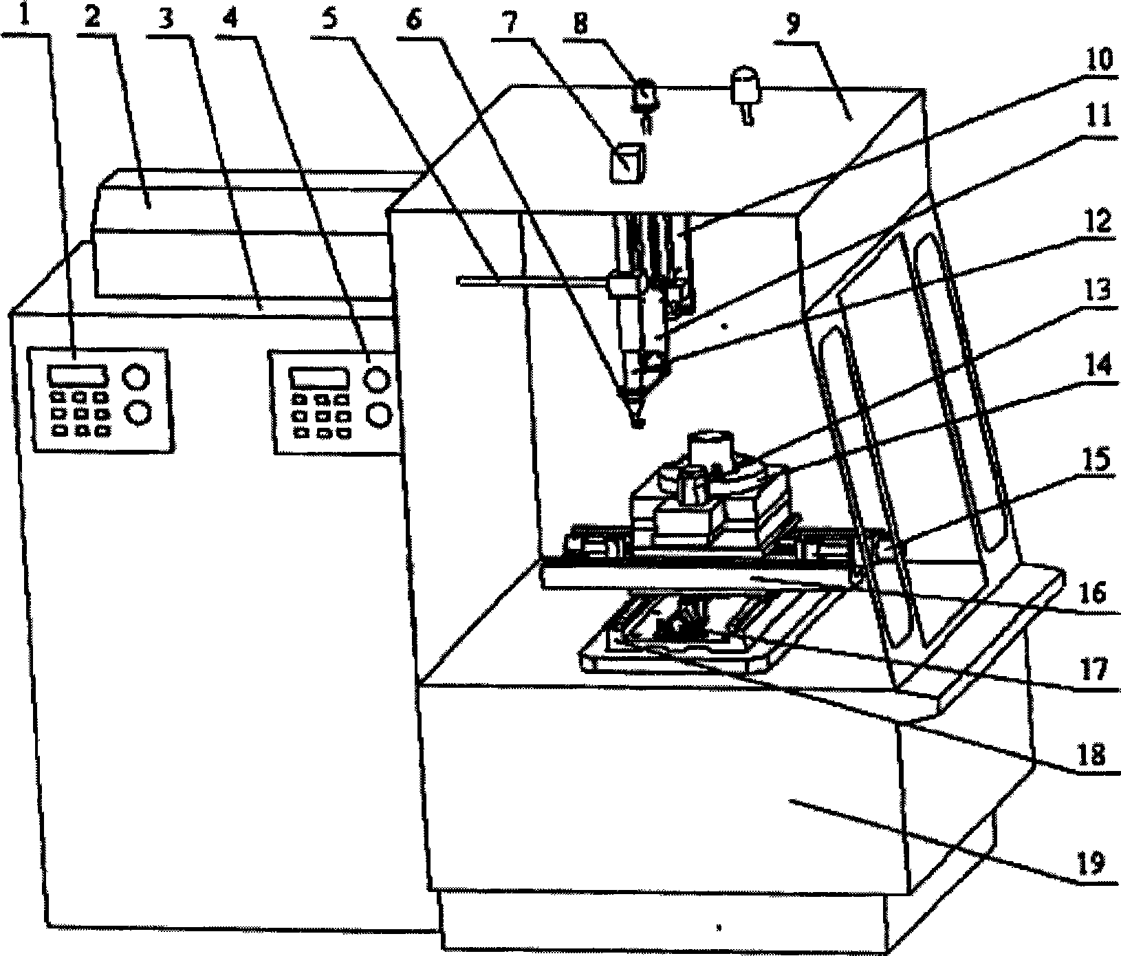
[0038] Such as Figure 8 In this embodiment, the surface of the cylinder liner workpiece 35 in the cylinder liner workpiece / piston ring system is processed with micro-recessed cavities, or crossed micro-recessed cavities or a combination of both.

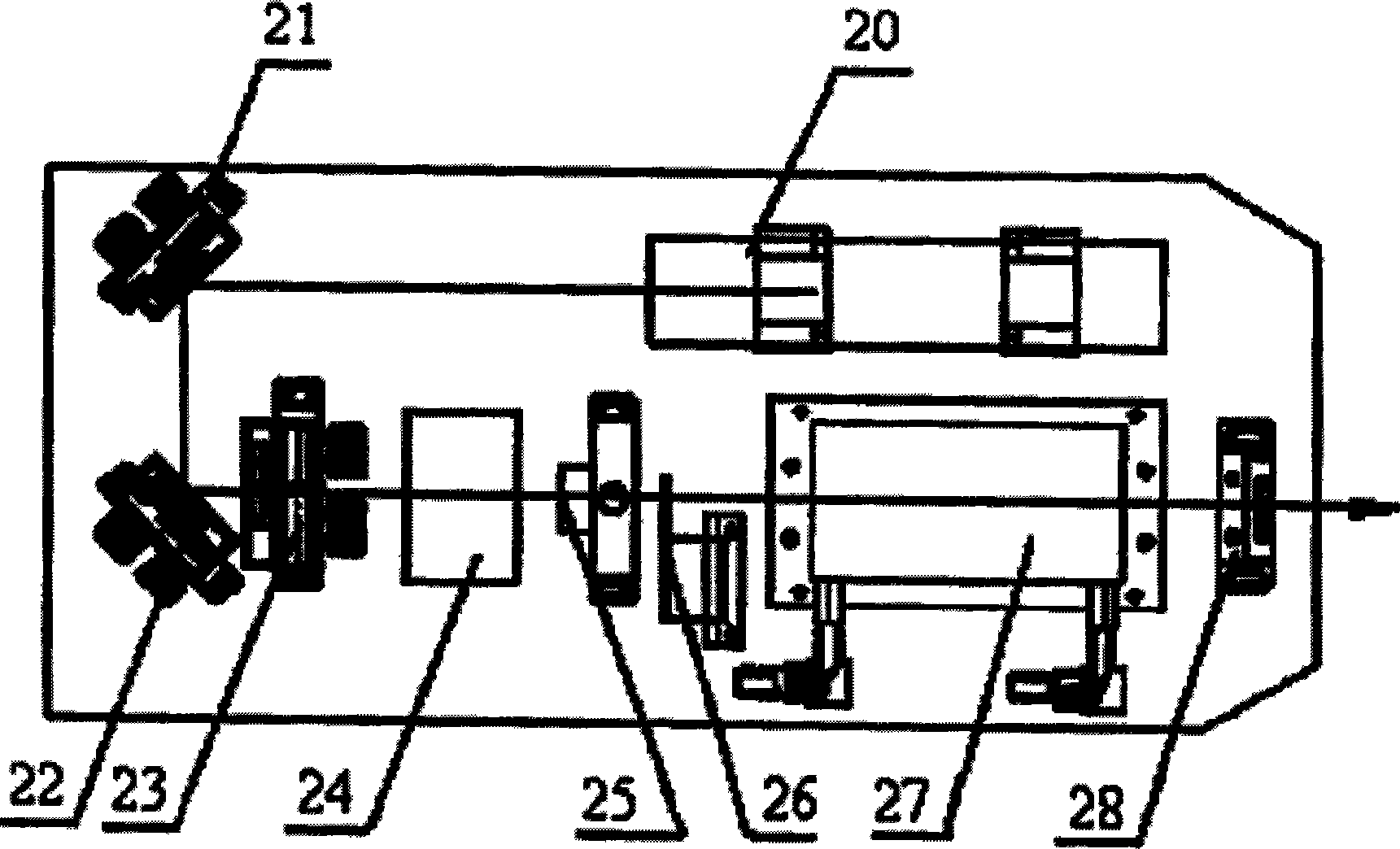
[0039] A flat base 19 is used to fix the X-direction guide rail 18 on it. The servo motor 17 of the model MSMA102A1G drives the Y-direction guide rail platform to move left and right along the guide rail 18 through the ball screw; the servo motor 15 of the model MSMA102A1G drives the turntable through the ball screw Move back and forth along the guide rail 16; the servo motor 13 of the model MSMA102A1C drives the main shaft 14 to rotate through the belt drive, and an incremental encoder of the type 1fa-500a-25000 is installed in the coaxial direction of the main shaft 14; the servo of the model is MSMA022A1A The motor 8 drives the telescopic frame 11 to move up and down along the Z-direction vertical guide rail 10 through the ball s...

Embodiment 2

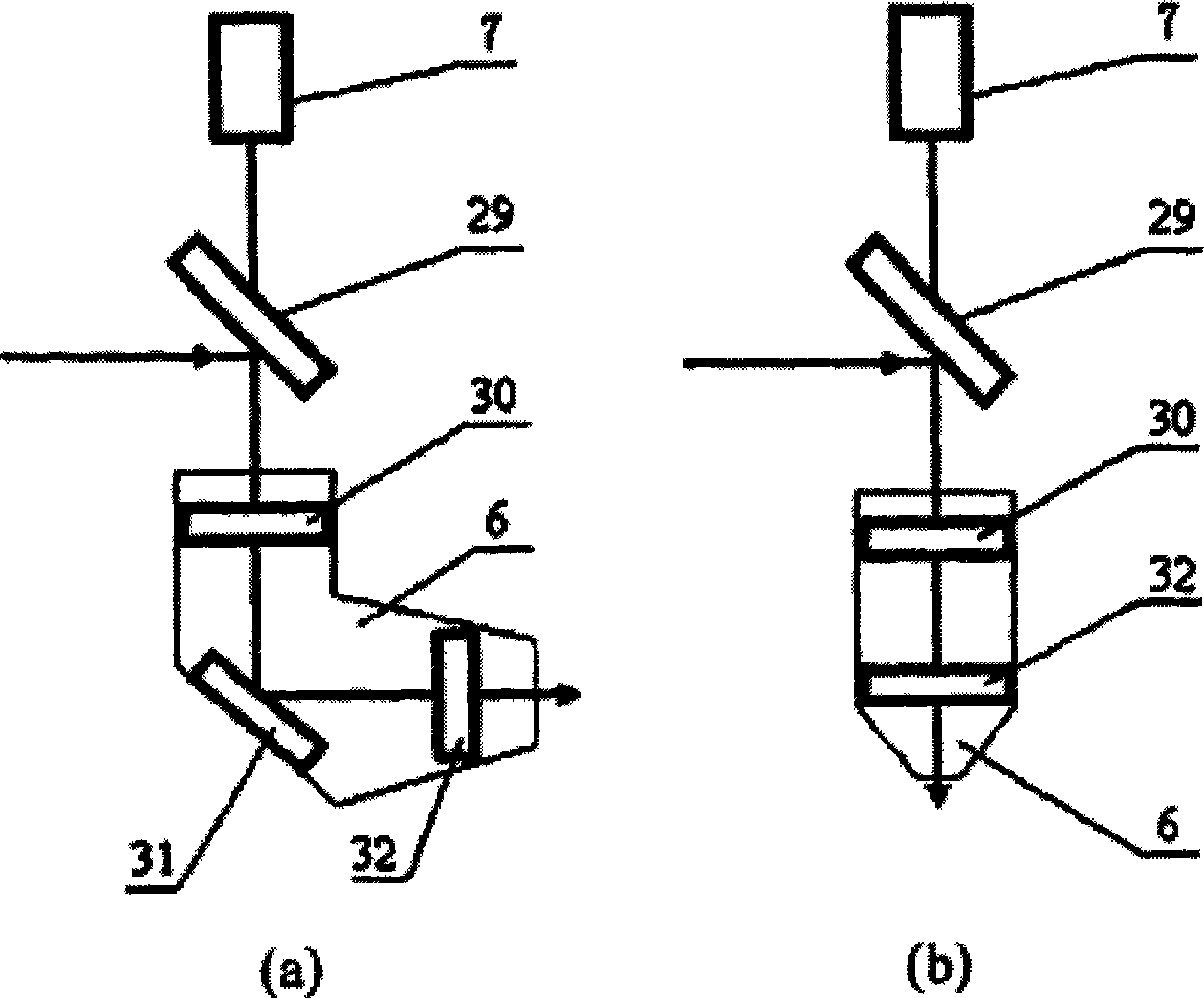
[0046] Such as Figure 10-12 As shown, the micro-cavity 39 and the micro-groove 38 are processed on the zero-leakage non-contact new mechanical seal ring workpiece 36. The basic principle is the same as the processing of the cylinder liner workpiece 35 in Embodiment 1, except that the end face of the seal ring is flat. So the laser processing nozzle consists of image 3 The elbow in (a) becomes image 3 Straight head in (b). Such as Figure 11 , when processing wide spiral grooves 40 with a depth of 1um to 20um and a width of more than 1mm, it can be completed by overlapping the concave cavities into narrow grooves, and then overlapping the narrow grooves into wide grooves , the shape of this macroscopic shallow groove, such as arc groove, spiral groove, etc., can be realized by the control software.


PUM

PropertyMeasurementUnit
Diameteraaaaaaaaaa
Depthaaaaaaaaaa
Widthaaaaaaaaaa

Abstract

The invention discloses a laser surface micro-processing device and a method thereof. The laser surface micro-processing device consists of a laser, an external light path part, a rotating and moving workpiece as well as a control part controlling the laser and the rotating and moving of the workpiece. After the processed workpiece moves in a rotating way with a main shaft, a pulse signal which shows the rotating position of the workpiece is output by an incremental encoder, thus leading the pulse emitting time of the laser to be coupled with the rotating time of the workpiece and just walking through the rotating distance between two processing points on the workpiece in the clearance time of two or a plurality of pulses; the control signal of an acoustooptic Q switch output by an industrial personal computer after frequency demultiplication controls the laser to output a single-pulse laser beam; a four-shaft moving control card controls the moving of a two-dimensional lead rail and a lead rail to lead the laser beam and the surface of the workpiece to generate feed movement for processing a micro concave cavity and a micro groove. The invention can lead the adverse thermal effect brought by the laser during processing to be reduced to be lowest and can ensure the surface processing quality of a feature to the largest extent simultaneously when considering the processing efficiency and processing cost.

Description

technical field [0001] The invention relates to the field of laser micromachining, in particular to a laser surface micromodeling technology capable of processing micro-cavities and micro-grooves on the surface of a workpiece. Background technique [0002] Machining an appropriate surface micro-morphology on the surface of the friction pair can significantly improve the lubrication performance of the friction pair and increase the service life of the friction pair. In order to meet these requirements, it is necessary to ensure the surface processing quality of the topography; at the same time, in order to promote the application in the field of industrial production, it is necessary to improve the processing efficiency and reduce the cost as much as possible. [0003] Laser surface micromodeling technology is an easy-to-control, high-efficiency modern processing method. However, the existing technology is not yet mature for industrial production, especially for the surface ...

Claims


Application Information

Patent Timeline
IPC IPC(8): B23K26/00B23K26/04B23K26/08G02B17/06B23K26/352
Inventor 符永宏米涛
Owner JIANGSU UNIV
Learn More